Computers / Cooling Systems
User Guide for MSI MAG FORGE 110R / 111R / 112R PC Case
Quick setup guide for the MSI MAG FORGE 110R, 111R, and 112R PC cases. Includes installation steps for components, IO panel layout, and ARGB fan connection instructions.
Table of contents
Manual images
Click an image to enlargeQuick Guide from the Manual
This document provides installation and setup instructions for the MSI MAG FORGE 110R, 111R, and 112R PC cases. It covers component installation, IO panel usage, and ARGB fan control board configuration.
Accessories
Ensure all parts are present before starting assembly:
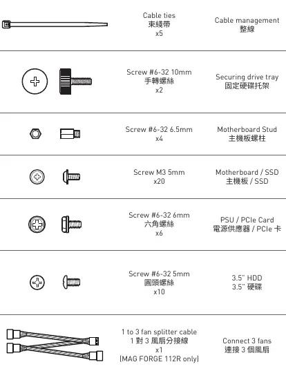
- Cable ties (x5) for cable management.
- Screw #6-32 10mm (x2) for securing drive trays.
- Screw #6-32 6.5mm (x4) for motherboard studs.
- Screw M3 5mm (x20) for motherboard/SSD.
- Screw #6-32 6mm (x6) for PSU/PCIe cards.
- Screw #6-32 5mm (x10) for 3.5" HDD.
- 1 to 3 fan splitter cable (x1, MAG FORGE 112R only).
Specifications
Key technical specifications for the case:
- Size: Mid-Tower.
- Motherboard Support: ATX, M-ATX, ITX.
- CPU Cooler Height: Max 160mm.
- Graphics Card Length: Max 330mm.
- PSU Length: Standard ATX 160mm (Max 200mm without 3.5" HDD tray).
- Fan Support: Top (2x 120/140mm), Front (3x 120mm / 2x 140mm), Rear (1x 120mm).
Case Features and IO Panel
The IO panel is located on the top of the case and includes:
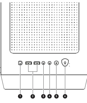
- LED switch button.
- 2x USB 3.2 Gen 1 Type-A ports.
- Mic-in jack.
- Line-out jack.
- Reset button.
- Power button.
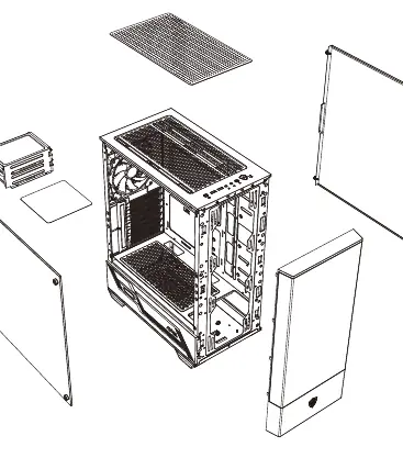
Installation Procedures
Follow these steps for component installation:
- Side Covers: Remove the left and right side panels by unscrewing the thumbscrews at the rear.
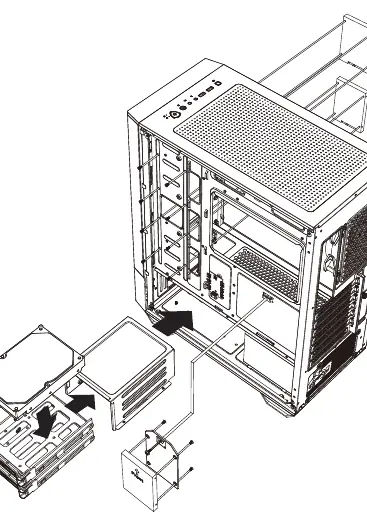
- SSD/HDD: Install drives into the drive trays or mounting brackets using the provided screws.
- Motherboard: Secure the motherboard to the standoffs using the M3 5mm screws.
- Graphics Card: Remove the expansion slot covers and secure the GPU using the #6-32 6mm screws.
- PSU: Slide the power supply into the bottom chamber and secure it from the rear.
ARGB Fan Connection and Control
The MAG FORGE 111R/112R includes an ARGB control board. To connect fans:
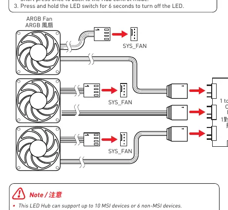
- Connect the ARGB fans to the 3-pin headers on the control board.
- Connect the SATA power cable from the control board to the PSU.
- Connect the control board to the motherboard JRAINBOW header for software synchronization.
- LED Control: Use the LED switch button to cycle through effects. Press and hold for 3 seconds to enter Mystic Light sync mode (LED flashes white). Press and hold for 6 seconds to turn off the LEDs.
Note: The LED hub supports up to 10 MSI devices or 6 non-MSI devices. Each port supports a maximum of 64 ARGB LEDs, with a total limit of 128 LEDs.
Practical help
Common problems
ARGB LEDs displaying abnormal colors or flickering
Ensure the total number of LEDs does not exceed 128 (max 64 per port) and the device count does not exceed 10 MSI or 6 non-MSI devices.
Cannot change LED colors via software
Ensure the hub is in synchronization mode by pressing and holding the LED switch for 3 seconds until the LED flashes white.
Before use
- Verify all screws and accessories are present.
- Check CPU cooler height clearance (max 160mm).
- Check GPU length clearance (max 330mm).
- Ensure PSU length is within limits (160mm standard, 200mm max without HDD tray).
- Confirm motherboard form factor compatibility (ATX, M-ATX, ITX).
Images and diagrams
- The ARGB connection diagram shows how to daisy-chain fans to the hub and connect the hub to the PSU and motherboard.
Model compatibility
- MAG FORGE 112R includes a 1-to-3 fan splitter cable.
- MAG FORGE 111R and 112R include the ARGB control board; 110R does not.

Manual page author
Emily Carter
User documentation editor
Prepares concise manual descriptions and highlights the most useful setup, operation, and maintenance information for readers.