Electronics / Networking
User Manual for ROLINE 21.13.1131 Industrial Managed Gigabit Ethernet Switch
Quick guide for the ROLINE 21.13.1131 industrial managed switch. Includes installation steps, DIN-rail mounting, power connection, PoE setup, and configuration instructions.
Table of contents
Manual images
Click an image to enlargeQuick guide from the manual
This document provides essential instructions for installing and configuring the ROLINE 21.13.1131 industrial managed switch. Key tasks include proper power connection, mounting the device, and initial network configuration. Always ensure the device is installed in a restricted area by authorized personnel due to high surface temperatures during operation.
Product description
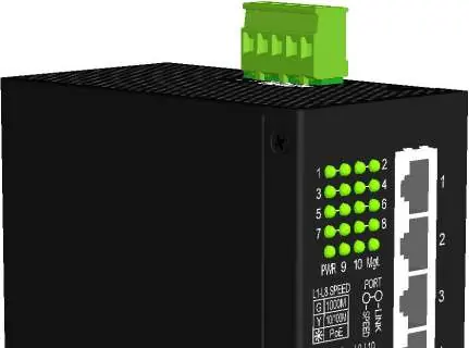
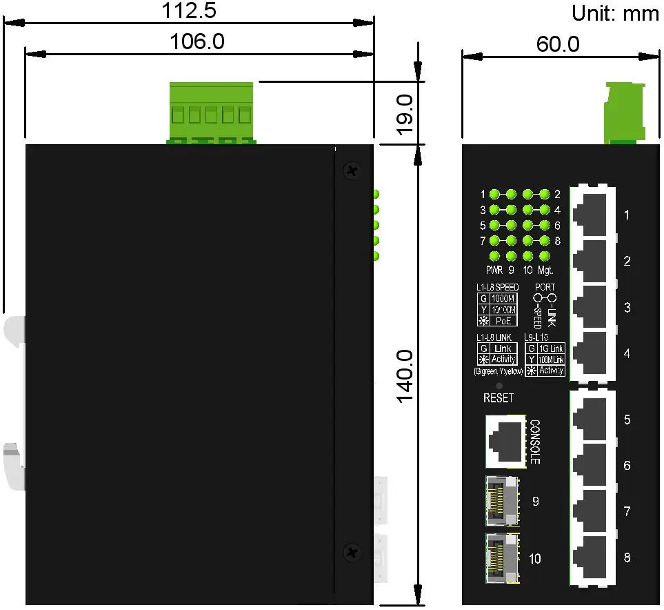
The ROLINE 21.13.1131 is a 10-port industrial managed Gigabit Ethernet switch. It features eight 10/100/1000Mbps copper ports with PoE functionality, two dual-speed SFP slots for fiber connectivity, and one RS-232 console port for management.
Installation
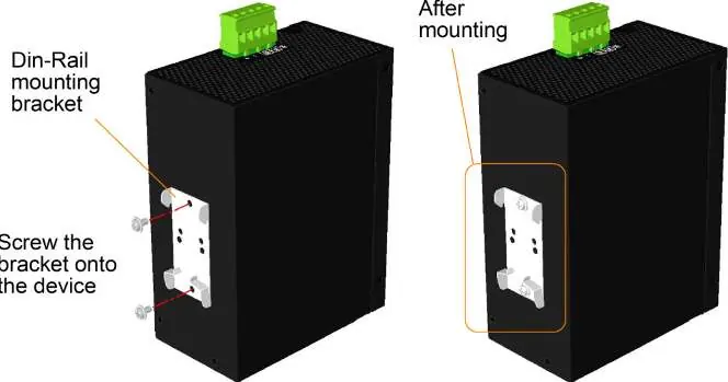
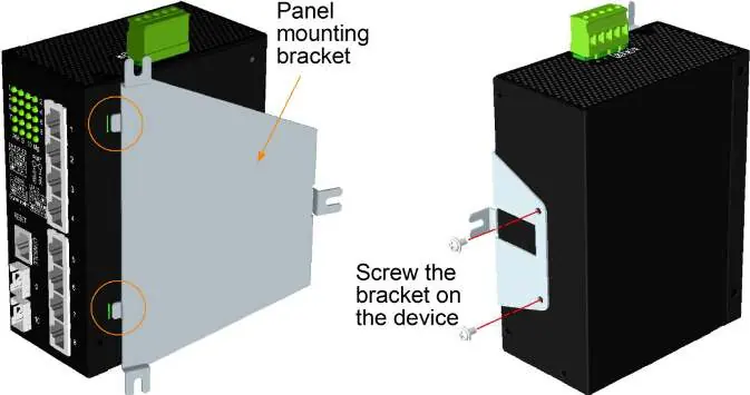
The switch supports both DIN-rail and panel mounting. For DIN-rail installation, attach the provided bracket to the switch, hook it onto the lower edge of the rail, and push upward until it clamps securely. For panel mounting, use the optional bracket to secure the device to a flat surface.
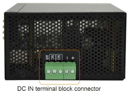
Power connection: The switch uses a terminal block connector. Connect DC power to the terminal block pins (Pin 1: Vdc+, Pin 2: Vdc-). Operating input voltages are +12 to +60VDC for general applications and +45 to +57VDC for PoE applications.
Alarm relay: The device includes an alarm relay output for reporting failure events like power loss or port link faults. It supports both Normally Open (NO) and Normally Closed (NC) logic.
Connections
UTP Connections: Use Cat.5 or higher cables for 10/100/1000Mbps connections. The ports support auto-MDI/MDI-X and auto-negotiation.
Fiber Connections: Install SFP fiber transceivers into ports 9 and 10. Ensure the Rx-to-Tx connection rule is followed on both ends of the fiber cable.
PoE PSE Connections: Ports 1-8 support IEEE 802.3af/at/bt standards. The switch automatically detects compliant Powered Devices (PD) and supplies power accordingly. The total power budget shared by all PSE ports is 240W.
Configuration
The switch is managed via Web interface, Telnet, Console, or SNMP. The factory default IP address is 192.168.0.2 with a subnet mask of 255.255.255.0. The default username is admin, and no password is required by default. It is highly recommended to change these credentials before deployment.
Redundant ring applications
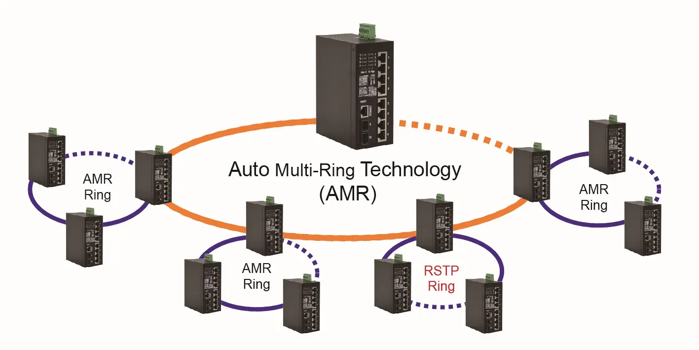
The switch supports Auto Multi-Ring (AMR) technology and the industrial standard RSTP protocol. AMR allows for fast failover and auto-recovery in ring topologies, supporting up to five rings and 30 member switches per ring.
Specifications
The device operates in temperatures ranging from -30°C to +70°C. It features a fanless metal housing and supports a relative humidity of 5% to 95% (non-condensing). LED indicators provide status for power, management, port speed, PoE, and link activity.
Manufacturer information
ROLINE
Practical help
Common problems
Network hanging or unresponsive
Press the reset button to perform a reboot without cycling the power.
PoE device not receiving power
Ensure the connected device is IEEE 802.3af/at/bt compliant. Non-compliant devices are not supported.
Cannot access web management interface
Ensure your computer is on the same subnet as the switch (default IP 192.168.0.2).
Before use
- Verify the DC power source voltage (12-60VDC for general, 45-57VDC for PoE).
- Ensure the DIN-rail or panel mounting bracket is securely attached.
- Identify TX and RX connectors before making fiber cable connections.
- Use Cat.5 or higher cabling for PoE applications.
- Change the default admin credentials before network deployment.
Specs in practice
- PoE Power Capacity
- 240W total power budget shared across all PSE ports.
- Operating Temperature
- Typical range is -30°C to +70°C.
- Alarm Relay Output
- Supports 30VDC/1A max. or 120VAC/0.5A max.
Images and diagrams
- Front Panel: Illustrates LED indicators, reset button, console port, and ports 1-10.
- DIN-Rail Mounting: Shows the bracket attachment and clamping procedure.
- Fiber Connection: Illustrates the required Rx-to-Tx cross-connection rule.
Model compatibility
- PoE: Supports IEEE 802.3af, 802.3at, and 802.3bt standards.
- Fiber: Supports 100Base-FX and 1000Base-X SFP transceivers.

Manual page author
David Miller
Documentation analyst
Organizes user manual content into clear summaries, with attention to model details, product context, and everyday usability.