Electronics / Networking
Leonton RPG5-2812-SFP8-10GSFP4 Industrial Managed Gigabit Switch User Guide
Quick guide for the Leonton RPG5-2812-SFP8-10GSFP4 industrial managed Gigabit switch. Includes installation steps, wiring diagrams for power and relay, LED indicator meanings, and troubleshooting tips.
Table of contents
Manual images
Click an image to enlargeQuick guide from the manual
The Leonton RPG5-2812-SFP8-10GSFP4 is an industrial managed Gigabit Ethernet switch designed for harsh environments. It features 16 PoE+ ports, 4 SFP+ ports, and 8 SFP slots. This guide covers essential installation, wiring, and troubleshooting procedures.
Hardware Description
The front panel includes power connectors, console port, USB port, DI/Relay terminal block, and various Ethernet/SFP ports. LED indicators provide real-time status of power, network activity, and PoE load.
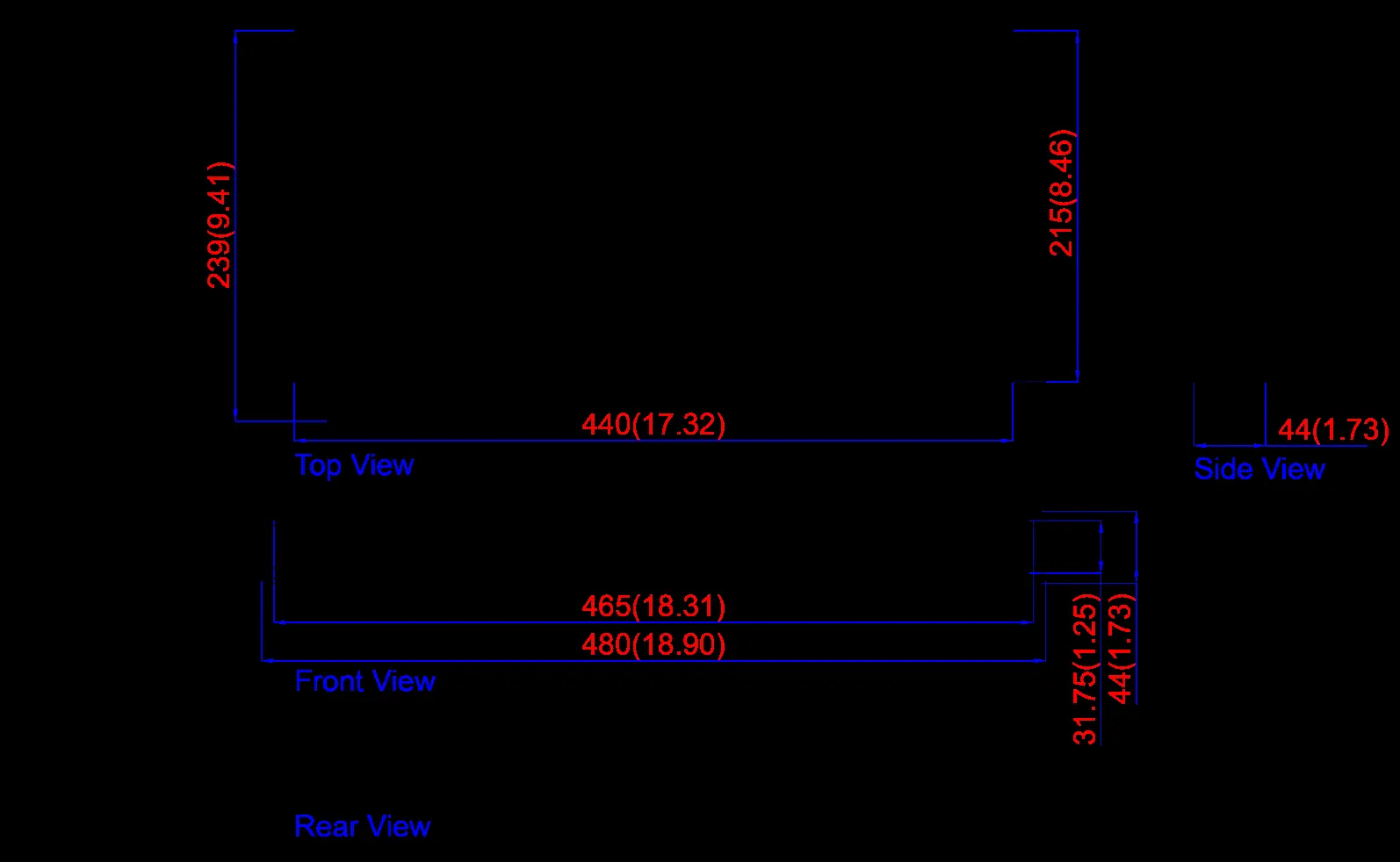
Mounting Installation
The switch is designed for rack-mounting. Attach the provided rack-mount brackets to both sides of the switch using the included screws, then secure the unit into a standard 19-inch rack.

Hardware Installation
Steps:

- Unpack the switch.
- Ensure rack-mount brackets are installed if necessary.
- Connect power to the terminal block (see Wiring section).
- Connect Ethernet cables (Cat 5e or better) to the RJ-45 ports.
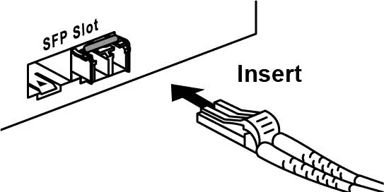
- Connect SFP modules and fiber cables to the SFP ports.
- Verify connections using the LED indicators.
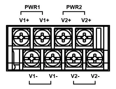
Wiring the Power Inputs
The switch supports dual 48-55VDC redundant power inputs. Use copper conductors (125°C) with a wire gauge between 18-20 AWG. Tighten terminal block screws to 7 in-lbs (0.79 Nm).
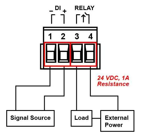
Relay Contact and Digital Input
The terminal block includes pins for Relay and Digital Input (DI). The relay detects fault status (power failure, DI event, or port link failure). The DI monitors external events via an external voltage source (Level 0: -30~8VDC, Level 1: 10~30VDC).
Troubleshooting
If the power LED does not turn on, check the power cord and connections. If packets are not transmitting, verify the Ethernet device configuration. If using only one power source, jumper Pin 1 to Pin 5 and Pin 2 to Pin 6 to eliminate power fault alarms.
Practical help
Common problems
Power LED does not turn on
Check the power cord, ensure connections are secure, and verify the power outlet for power losses or surges.
Packets not transmitting
Verify the system's Ethernet device configuration and status.
Power fault alarm triggered
If using only one power source, jumper Pin 1 to Pin 5 and Pin 2 to Pin 6 to eliminate the alarm.
Before use
- Verify power supply voltage is 48-55VDC.
- Ensure Cat 5e or better cabling is used for RJ-45 ports.
- Confirm cable length is under 100 meters.
- Ensure rack-mount brackets are securely attached.
- Verify proper grounding connection using the ground screw.
Specs in practice
- Operating Temperature
- Standard model: -10°C to 65°C; Extended (-T) model: -40°C to 75°C.
- Relay Contact
- 24VDC, 1A resistive for fault monitoring.
- Digital Input
- Monitors external events; Level 0: -30~8VDC, Level 1: 10~30VDC.
Images and diagrams
- Figure 2.2: Front panel layout showing ports, LEDs, and connectors.
- Figure 2.9: Power input terminal block wiring.
- Figure 2.10: Relay and Digital Input wiring diagram.
- Figure 3.1: Rack-mount bracket installation.
Model compatibility
- Requires UL Listed industrial power supply.
- SFP transceivers must comply with IEC 60825-1 (Class 1 laser product).

Manual page author
Emily Carter
User documentation editor
Prepares concise manual descriptions and highlights the most useful setup, operation, and maintenance information for readers.