Plumbing / Toilets Urinals
Installation and User Guide for Sanela SLW 02PA Piezo Toilet Flushing Unit
Comprehensive installation and operation guide for the Sanela SLW 02PA Piezo Toilet Flushing Unit. Includes mounting instructions, electrical connection, parameter settings, and maintenance tips.
Table of contents
Manual images
Jump to the sectionQuick guide from the manual
The Sanela SLW 02PA is a piezo-controlled toilet flushing unit designed for in-wall installation. Crucial: The unit requires a constant 24V DC power supply. Do not connect the power supply behind a light switch, as this will cause the unit to malfunction. Ensure the water pressure is maintained between 0.1 and 0.6 MPa for proper operation.
Installation
The unit includes the SLR 21 mounting frame. Follow these steps for installation:
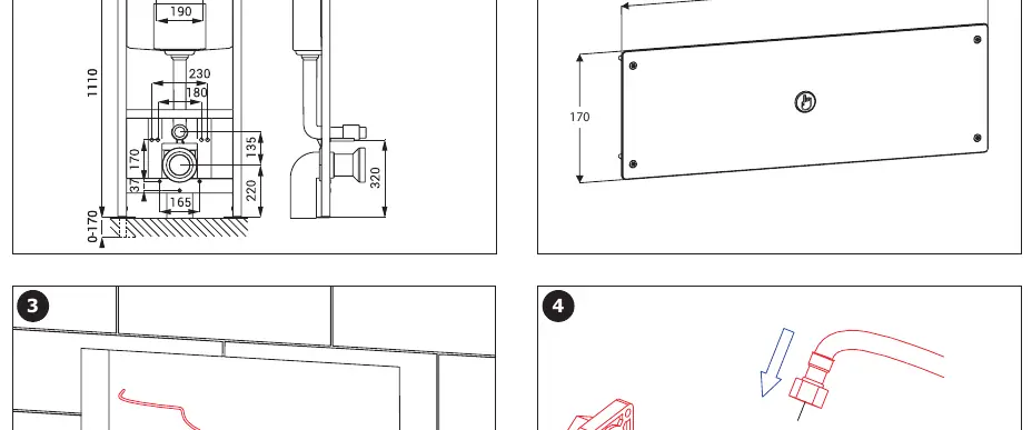
- Prepare the wall recess according to the frame dimensions.
- Install the mounting frame securely into the wall.
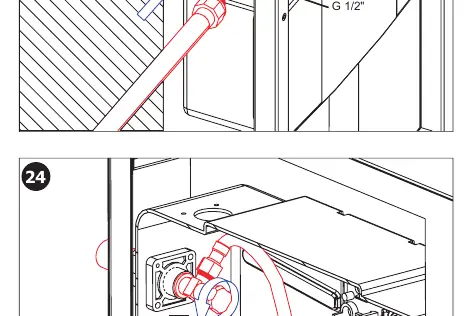
- Connect the water supply (G 1/2") to the flushing mechanism.
- Ensure the sieve is installed to prevent debris from entering the valve (sieve dimension ≤ 90 µm).
- The installation process differs slightly depending on whether you are using a ceramic or stainless steel toilet; ensure you use the correct mounting parts provided in the kit.
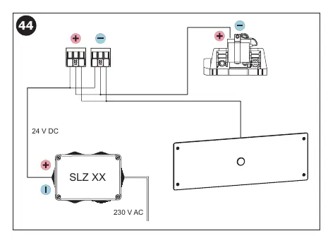
Electrical connection
The unit operates on 24V DC. Connect the power supply unit to the flushing unit. Ensure the connection is permanent and not controlled by any external light switches. Refer to the wiring diagram on page 8 for the correct connection of the power supply (SLZ XX) to the flushing unit.
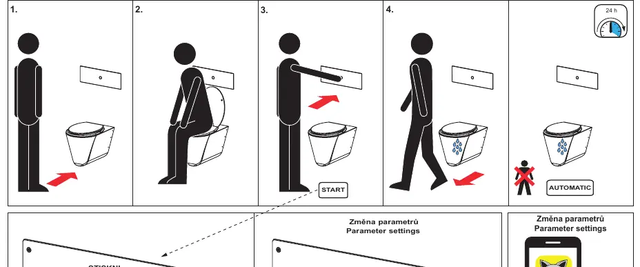
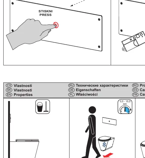
Operation and settings
The unit is operated via a piezo button. It features an automatic hygienic flush function. You can adjust parameters such as flush time and hygienic flush intervals using the SLD 04 remote control. The factory setting for the flush time is 5 seconds.
Maintenance
Clean all stainless steel components using only water, soap, and a soft cloth. It is strictly forbidden to use aggressive or abrasive cleaning agents. The manufacturer recommends using the SLA 37 cleaning product for maintenance.
Manufacturer information
SANELA spol. s r. o.
Practical help
Common problems
Unit does not flush or operates intermittently
Verify that the power supply is constant and not connected behind a light switch.
Water flow is weak or inconsistent
Check that the water pressure is within the 0.1 - 0.6 MPa range and ensure the sieve is not clogged.
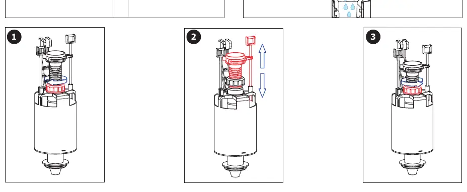
Flush volume needs adjustment
Use the SLD 04 remote control to adjust parameters or adjust the mechanical flush valve settings.
Before use
- Ensure a constant 24V DC power supply is available.
- Verify water pressure is between 0.1 and 0.6 MPa.
- Check that the power supply is not connected to a light switch circuit.
- Ensure the installation wall is prepared for the SLR 21 frame.
- Verify the sieve is clean and installed correctly.
Specs in practice
- Operating Pressure
- 0.1 - 0.6 MPa (Required for proper valve function).
- Sieve Dimension
- ≤ 90 µm (Maximum particle size allowed to prevent valve damage).
Images and diagrams
- Page 3: Frame installation and water connection details.
- Page 8: Electrical wiring diagram for 24V DC power supply.
- Page 10: Flush valve and water volume adjustment procedures.
Model compatibility
- Compatible with both ceramic and stainless steel toilets (requires different mounting hardware included in the kit).

Manual page author
Michael Turner
Technical manual editor
Reviews PDF manuals for structure, safety notes, and practical product details so readers can find the right information quickly.