Plumbing / Toilet Flushers
Installation and User Guide for Sanela SLW 02N Automatic Toilet Flusher
Comprehensive installation and user guide for the Sanela SLW 02N automatic toilet flusher. Includes wiring instructions, setup for the SLR 21 system, sensor operation, and maintenance requirements.
Table of contents
Manual images
Click an image to enlargeImportant Information
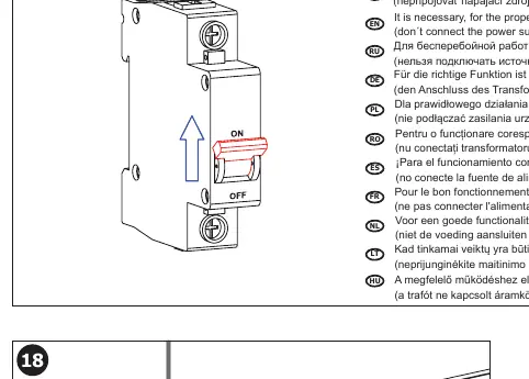
For the proper function of the Sanela SLW 02N, the unit must be kept under constant voltage. Do not connect the power supply unit behind a switch in the light circuit. This device is designed for use with the SLR 21 installation system.
Installation
The installation must be performed by qualified personnel. Ensure you have familiarized yourself with the safety instructions before beginning.
- Ensure the SLR 21 mounting frame is correctly installed in the wall.
- Verify the water supply pressure is between 0.1 and 0.6 MPa.
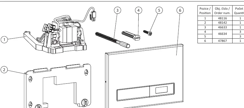
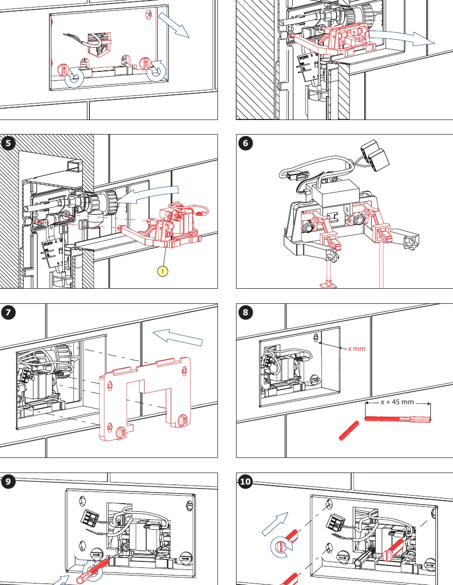
- Install the flushing unit into the frame according to the provided steps (1-16).
- Ensure the sieve dimension is less than or equal to 90 µm to prevent clogging.
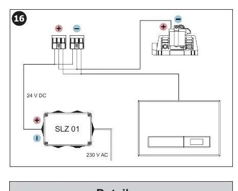
- Connect the 24V DC power supply.
Wiring and Power
The unit requires a 24V DC power supply. Refer to the wiring diagram on page 4 for correct connection. Ensure the power supply is constant and not interrupted by light switches or other external controls.
Operation and Settings
The unit features an infrared sensor for automatic flushing and a manual flush button. The sensor parameters (such as flush duration and detection range) can be adjusted using the SLD 03 remote control.
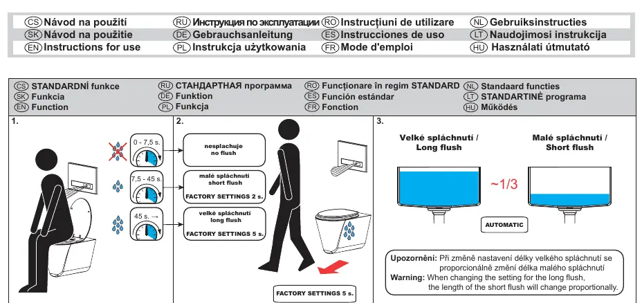
- Automatic Flush: Triggered by the infrared sensor.
- Manual Flush: Triggered by pressing the button on the unit.
- Settings: Use the SLD 03 remote control to adjust infrared sensor parameters.
Maintenance
Regular maintenance is recommended to ensure long-term reliability. Keep the sensor area clean and free of obstructions. If the unit fails to operate, check the power supply connection first.
Technical Specifications
- Operating Pressure: 0.1 - 0.6 MPa
- Power Supply: 24V DC
- Compatibility: SLR 21 installation system
- Sieve Dimension: ≤ 90 µm
Manufacturer information
SANELA spol. s r. o.
Practical help
Common problems
Unit does not flush automatically
Check if the power supply is connected and providing constant 24V DC. Ensure the sensor is not obstructed.
Incorrect flush duration
Use the SLD 03 remote control to adjust the flush parameters.
Before use
- Verify the SLR 21 mounting frame is installed.
- Ensure 24V DC power supply is available.
- Check water pressure is within 0.1 - 0.6 MPa.
- Ensure the sieve is clean (≤ 90 µm).
- Confirm power is not connected to a light switch.
Specs in practice
- Operating Pressure
- The water pressure must be between 0.1 and 0.6 MPa for the valve to function correctly.
- Power Supply
- Requires a constant 24V DC source.
- Sieve Dimension
- The filter mesh size must be 90 µm or smaller to protect the valve from debris.
Images and diagrams
- Wiring diagram shows the connection of the 24V DC power supply.
- Installation steps illustrate the mounting of the flushing unit into the SLR 21 frame.
Model compatibility
- Compatible with SLR 21 installation system.
- Requires SLD 03 remote control for parameter adjustments.
- Requires 24V DC power supply (e.g., SLZ 01Y, SLZ 01Z, SLZ 04Y, SLZ 04Z, SLZ 04X).

Manual page author
Emily Carter
User documentation editor
Prepares concise manual descriptions and highlights the most useful setup, operation, and maintenance information for readers.