Plumbing / Toilets Urinals
Installation Manual for Sanela SLWN 08L/08P Vandal-Proof Corner Combination Unit
A comprehensive installation and maintenance guide for the Sanela SLWN 08L and SLWN 08P vandal-proof corner combination units. Includes technical specifications, mounting steps, water flow regulation, and essential safety requirements.
Table of contents
Manual images
Click an image to enlargeImportant Information
Before beginning the installation, it is essential to thoroughly familiarize yourself with the attached Safety Instructions. Ensure that the water supply pressure is between 0.1 and 0.6 MPa. The water supply system must include a sieve with a dimension of ≤ 90 µm to prevent debris from damaging the unit.
Product Overview
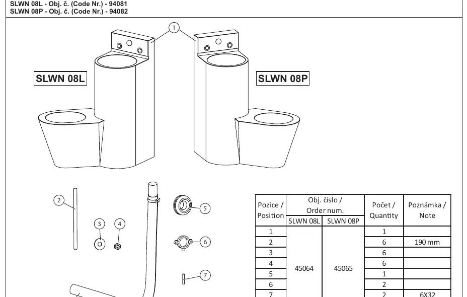
The Sanela SLWN 08L and SLWN 08P are vandal-proof corner combination units featuring a floor-standing toilet. The SLWN 08L is designed for the left side, while the SLWN 08P is designed for the right side.
Technical Specifications
- Water Pressure: 0.1 - 0.6 MPa
- Sieve Dimension: ≤ 90 µm
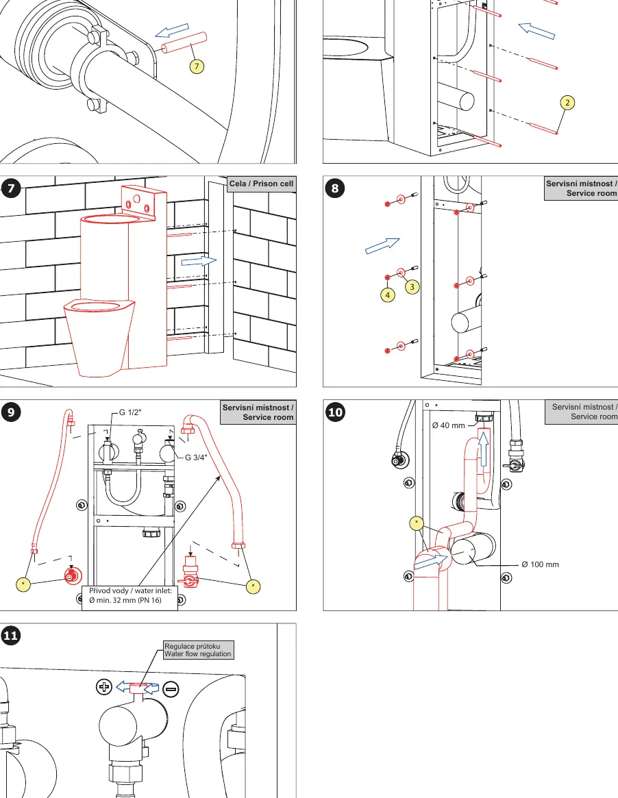
- Water Inlet: G 1/2" and G 3/4" connections
- Waste Outlet: Ø 100 mm
Installation
The installation requires preparation of the wall and service room area. Follow these steps:
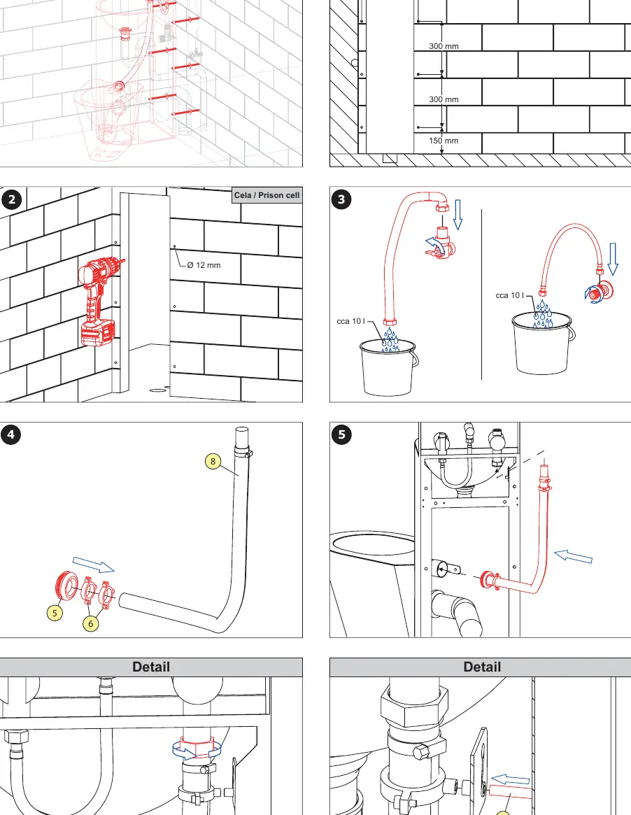
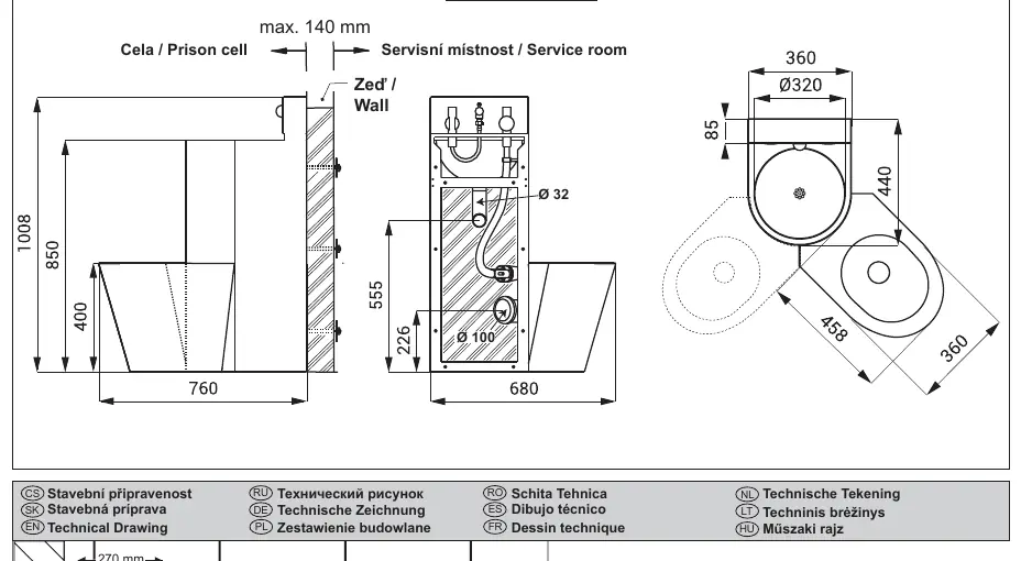
- Wall Preparation: Prepare the wall according to the technical drawing, ensuring the necessary clearances (e.g., 320 mm, 300 mm, 150 mm spacing).
- Mounting: Use the provided mounting hardware to secure the unit to the wall. Ensure the unit is level and stable.
- Water Connection: Connect the water supply to the G 1/2" and G 3/4" inlets. Ensure the water inlet pipe is at least Ø 32 mm (PN 16).
- Waste Connection: Connect the waste outlet (Ø 100 mm) to the sewage system.
- Final Assembly: Secure all components, including the toilet and sink assembly, using the supplied hardware (positions 1-8).
Water Flow Regulation
The unit features a water flow regulation valve. Use this valve to adjust the water flow to the desired level. Turn the regulator to the '+' or '-' positions to increase or decrease the flow.
Maintenance
Regular maintenance is recommended to ensure the longevity and proper operation of the unit. For technical support, service intervention, or fault resolution, contact the installation company or visit the official Sanela website at www.sanela.eu/service. Always follow the specific maintenance instructions provided on the website.
Official resources from the manual
Manufacturer information
SANELA spol. s r. o.
Practical help
Common problems
Low water flow
Adjust the water flow regulation valve located on the unit.
Debris in the system
Ensure the water supply system includes a sieve with a dimension of ≤ 90 µm.
Before use
- Verify water pressure is between 0.1 and 0.6 MPa.
- Ensure the wall is prepared according to the technical drawing.
- Read the attached Safety Instructions.
- Check that all supplied equipment (positions 1-8) is present.
- Ensure the water inlet pipe is at least Ø 32 mm.
Specs in practice
- Water Pressure
- Must be between 0.1 and 0.6 MPa for proper operation.
- Sieve Dimension
- Must be ≤ 90 µm to prevent clogging and damage to the unit.
Images and diagrams
- The installation involves mounting the unit to the wall, connecting the water inlet, and ensuring the waste pipe is correctly positioned.
- The technical drawing provides specific dimensions for wall preparation and service room layout.
Model compatibility
- The unit is designed for corner installation.
- SLWN 08L is for left-side installation.
- SLWN 08P is for right-side installation.

Manual page author
David Miller
Documentation analyst
Organizes user manual content into clear summaries, with attention to model details, product context, and everyday usability.