Software / Apps Services
Seagate Lyve Mobile Mount SMSE001 Installation Manual
Comprehensive installation and setup guide for the Seagate Lyve Mobile Mount (SMSE001). Includes instructions for surface mounting, stacking, device installation, cable management, and security configuration.
Quick answers from the manual
Quick answer
- The Seagate Lyve Mobile Mount (SMSE001) is a mounting solution for Lyve Mobile storage devices. It supports surface mounting, vertical/horizontal stacking, and includes cable management and security locking features. p. 1, 4, 5, 6
Key actions
- Mounting to a surface p. 4
- Stacking mounts p. 5
- Installing the device p. 7
Problems and fixes
Need to connect computer directly to Lyve Mobile Array
Remove the preinstalled guide pins from the bottom of the mount using a 6mm hex key wrench.
p. 6Show 2 more answers Show less
Technical specifications
| Parameter | Value | Meaning | Pages |
|---|---|---|---|
| Clearance Zone | 970 mm x 240 mm | Recommended space for Lyve Mobile Array and Mount. | p. 4 |
Where to find it in the PDF
- Part List p. 2
- Installation p. 4, 7
Table of contents
Manual images
Click an image to enlargeQuick guide from the manual
This document provides installation and setup instructions for the Seagate Lyve Mobile Mount (model SMSE001). It covers the physical installation of the mount to a surface, stacking multiple mounts, installing the Lyve Mobile Array, and configuring security settings.
Part list
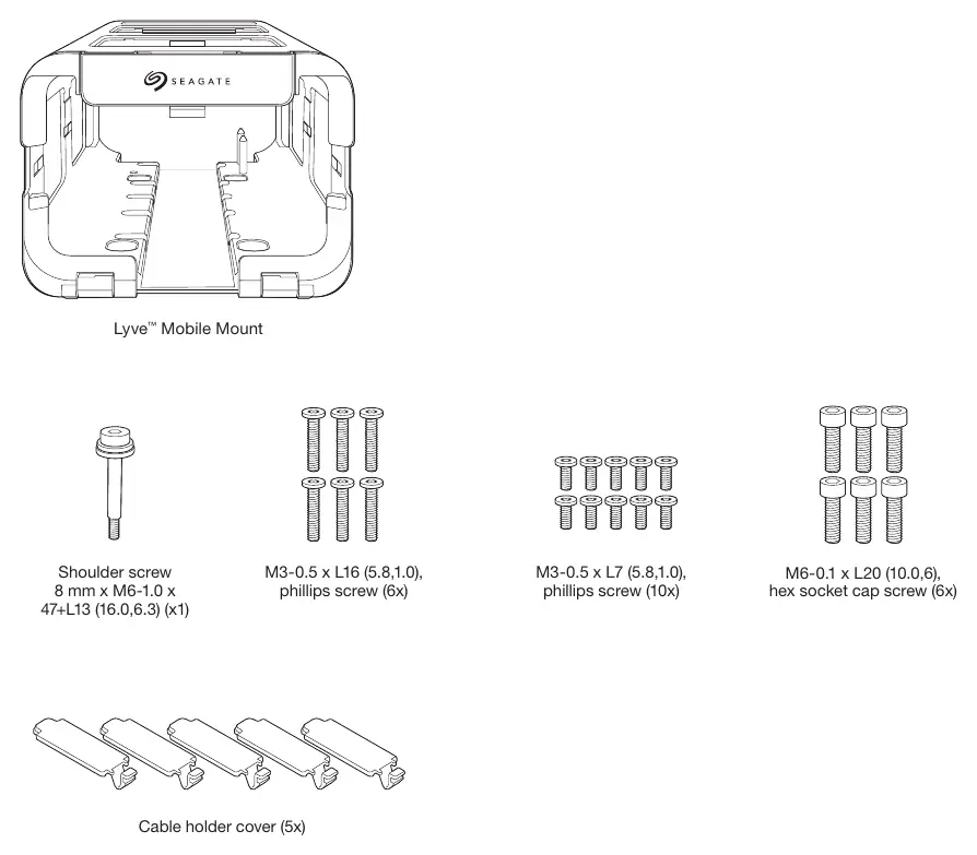
- Lyve Mobile Mount
- Shoulder screw (8 mm x M6-1.0 x 47+L13) (1x)
- M3-0.5 x L16 phillips screws (6x)
- M3-0.5 x L7 phillips screws (10x)
- M6-0.1 x L20 hex socket cap screws (6x)
- Cable holder covers (5x)
Setup requirements
Lyve Mobile offers two security management options for project administrators:
- Lyve Portal Identity: Requires internet connection for initial setup and periodic reauthorization via the Lyve Management Portal.
- Lyve Token Security: Uses token files installed on client computers or Lyve Mobile Padlock devices. Once configured, it does not require continual internet access.
For detailed security setup, visit www.seagate.com/lyve-security.
Mounting to a surface
Caution: This equipment is heavy. Use proper lifting techniques. Do not attempt to lift or assemble the mount with compatible devices inserted.
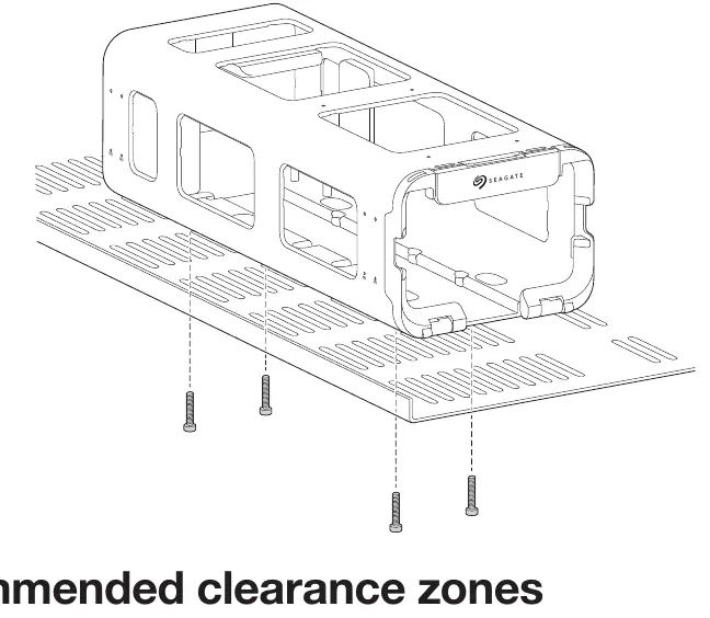
- Ensure the mount is securely fixed to the vehicle or surface to avoid motion.
- Use at least four M6-0.1 x L20 hex socket cap screws.
- Insert screws into the M6 tap holes on the bottom of the mount (two at the front, two at the back).
Clearance: Ensure a recommended clearance zone of 970 mm by 240 mm for the Lyve Mobile Array and Mount.
Connecting multiple mounts
Vertically: Stack two mounts and align the six attachment holes on the top and bottom. Secure using four M3-0.5 x L16 screws.
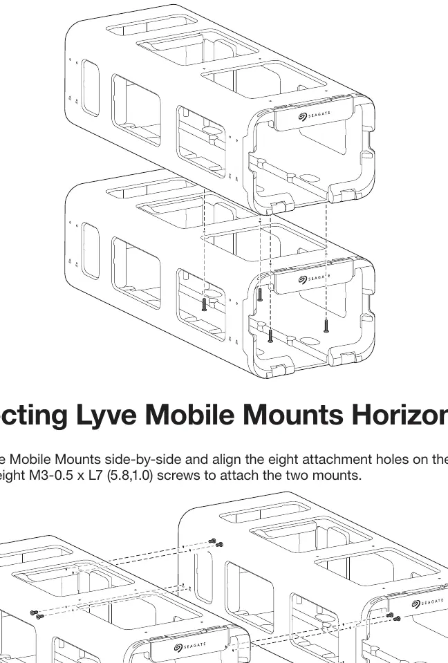
Horizontally: Place two mounts side-by-side and align the eight attachment holes on the sides. Secure using eight M3-0.5 x L7 screws.
Installing the device
- Release handle: Grasp the lock catch on the front of the mount and pull it forward to release the front lock bezel. Lower the bezel.
- Insert device: Slide the Lyve Mobile Array into the mount with the ports facing the back.
- Lock device: Raise the front lock bezel until it snaps into place.
Cable management
You can route cables through the front of the mount using the internal channel. Use the provided plastic cable holder covers to secure cables. Insert the rounded tab into the notch on the right side of the channel and snap the hooked release tab into the slot on the left.
Security
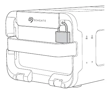
The front lock bezel and lock catch can be secured with a padlock (not included). Insert the padlock shackle through the openings on the right or left of the catch plate.
Official resources from the manual
Manufacturer information
Seagate Technology LLC
Practical help
Common problems
Heavy equipment handling
Always use proper lifting techniques. Do not attempt to lift or assemble the mount while the Lyve Mobile Array is inserted.
Guide pins interference
If connecting a computer directly to the Lyve Mobile Array's host port, remove the preinstalled guide pins from the bottom of the mount using a 6mm hex key wrench.
Before use
- Verify all screws are present according to the part list.
- Ensure the mounting surface is stable and can support the weight.
- Check that the clearance zone (970mm x 240mm) is clear.
- Determine if you need to remove guide pins for your specific connection type.
- Decide on security method (Portal Identity vs. Token Security).
Show more Show less
Specs in practice
- Clearance Zone
- Required space of 970 mm x 240 mm for the Lyve Mobile Array and Mount.
- Mounting Screws
- Use M6-0.1 x L20 hex socket cap screws for surface mounting.
Images and diagrams
- The manual provides diagrams for vertical and horizontal stacking of multiple mounts.
- Installation steps clearly show the release handle mechanism and device insertion direction.
- Cable routing diagram illustrates the use of the internal channel and cable holder covers.
Model compatibility
- Guide pins are preinstalled for use with a PCIe Adapter.
- Remove guide pins if connecting a computer directly to the Lyve Mobile Array's host port.

Manual page author
David Miller
Documentation analyst