Tools / Tool Storage
User Manual for Sealey 7 Drawer 1415mm Topchest and 11 Drawer 1430mm Rollcab
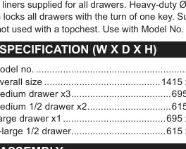
Quick guide for the Sealey 7 Drawer 1415mm Topchest (PTB141507) and 11 Drawer 1430mm Rollcab (PTB143011). Includes assembly instructions, drawer operation, maintenance, and safety guidelines.
Table of contents
Manual images
Click an image to enlargeQuick guide from the manual
This manual provides assembly, operation, and maintenance instructions for the Sealey 7 Drawer 1415mm Topchest (PTB141507) and 11 Drawer 1430mm Rollcab (PTB143011). Due to the weight of these units, assembly requires two people. Always ensure the units are placed on level, solid ground and that drawers are closed and secured before moving the rollcab.
Safety
- Locate the rollcab and topchest in a suitable, well-lit work area.
- Always use the units on level and solid ground, preferably concrete.
- Keep children and unauthorized persons away from the work area.
- Do not step on the drawers.
- Do not move the rollcab with the drawers open. Close and secure all drawers before moving.
- Do not use solvents to clean the surfaces as this may damage the protective coating.
Assembly
Rollcab Handle Installation
Position the handle over the holes in the rollcab and attach it using the provided M6 x 12mm hex bolts. Tightening the handle first makes the rollcab easier to maneuver.
Castor Installation
- Lay the rollcab on its back carefully, using a soft mat to protect the surface.
- Position the two rigid wheels in the center of the rollcab base.
- Insert M8 x 20mm hex bolts through the washers and brackets into the base, tightening securely.
- Repeat the process for the two swivel castors at each outer end.
- Stand the rollcab upright carefully.
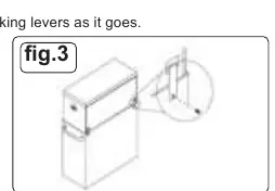
Rollcab and Topchest Connection
- Remove the worktop from the rollcab.
- Place the topchest onto the rollcab.
- Insert the connectors into the rectangular holes on the back of the topchest.
- Fasten the connectors using the provided screws.
Operation
Lift Latch Drawers
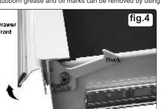
To open a drawer, lift the drawer front while pulling it out. To close, push the drawer firmly until the latch engages. If the drawer does not latch, the hook may be misaligned; gently bend the hook until it is parallel to the drawer edge.
Removing Drawers
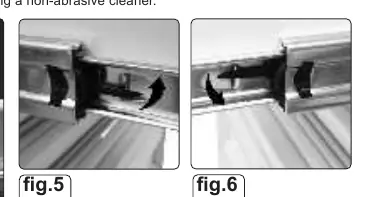
- Pull the drawer out almost fully.
- Locate the black locking levers on the slides.
- Facing the drawer, lift one lever up and push the other lever down simultaneously.
- With both levers held in this position, pull the drawer out from the slides.
Replacing Drawers
- Extend the drawer runners from the cabinet.
- Carefully engage the slides on either side of the drawer into the runners.
- Push the drawer closed squarely until it is fully closed and the locking levers engage.
Maintenance
- Lubricate the drawer slides sparingly every six months.
- Clean the metalwork periodically with warm water and a mild detergent.
- Use car wax to restore the shine to the paintwork.
- Remove stubborn grease and oil marks using a non-abrasive cleaner.
Contact Information
Sealey Group, Kempson Way, Suffolk Business Park, Bury St Edmunds, Suffolk. IP32 7AR. Phone: 01284 757500. Fax: 01284 703534. Email: [email protected]. Website: www.sealey.co.uk.
Official resources from the manual
Manufacturer information
Sealey Group
Practical help
Common problems
Drawer does not latch when closed
The hook may be misaligned. Gently bend the hook until it is parallel to the drawer edge so it engages correctly.
Drawer cannot be removed
Ensure you are lifting one locking lever up and pushing the other lever down simultaneously while pulling the drawer.
Before use
- Ensure the floor is level and solid (preferably concrete).
- Verify that two people are available for assembly due to the weight of the cabinets.
- Check that all M6 and M8 bolts are tightened securely.
- Ensure the worktop is removed from the rollcab before mounting the topchest.
- Verify that the locking system is functional.
Images and diagrams
- Fig 1: Handle installation using M6 bolts.
- Fig 3: Connecting the top chest to the rollcab using provided connectors.
- Fig 4: Operation of the lift latch mechanism.
- Fig 5 & 6: Operation of the drawer removal levers.
Model compatibility
- The PTB141507 topchest is designed to be used with the PTB143011 rollcab or as a standalone unit.
- The PTB143011 rollcab includes a 12mm PVC coated MDF worktop for use when not paired with a topchest.

Manual page author
Emily Carter
User documentation editor
Prepares concise manual descriptions and highlights the most useful setup, operation, and maintenance information for readers.