Documents / Warranty Safety
Sealey Oil-Free Belt Drive Compressor (SAC00015, SAC00615, SAC02415)
Comprehensive operating and safety instructions for Sealey oil-free belt drive compressors, covering models SAC00015, SAC00615, and SAC02415.
Table of contents
Product Overview
The Sealey oil-free belt drive compressor range, including models SAC00015, SAC00615, and SAC02415, is designed for applications requiring clean, oil-free air delivery. These units are ideal for small-scale, low-pressure tasks such as airbrushing, touch-up painting, and general-purpose pneumatic applications. Their simple construction and reduced weight ensure high portability and ease of use.
Safety Guidelines
Safety is paramount when operating compressed air equipment. Users must ensure the compressor is placed on a stable, level surface in a well-ventilated area. Always wear appropriate eye and ear protection. Never direct the air jet toward people or animals. The compressor must be kept away from flammable liquids, gases, or solids. Do not touch the cylinder head during or shortly after operation, as it becomes extremely hot. The unit should never be left running unattended, and unauthorized persons or children must be kept away from the working area.
Operation and Duty Cycle
Before operation, ensure the mains voltage matches the compressor data plate. Connect the air tool to the outlet and switch the unit on. For models with tanks, output pressure can be regulated using the pressure regulator tap. These compressors operate on a 25% duty cycle; for every period of use, a rest period three times that length is required to prevent motor overheating. If the thermal cut-out triggers, the motor will stop and restart automatically once it has cooled down. Always vent remaining pressure and drain moisture from the tank after use to prevent internal corrosion.
Maintenance and Troubleshooting
Regular maintenance is essential for longevity. Keep the compressor clean and free of dust by wiping it with a damp cloth and using compressed air to clear ventilation openings. Periodically drain the tank using the drainage tap at the bottom. If performance drops, first check that the air tool is clean and functioning correctly. If issues persist, such as frequent start-ups or air leaks, consult the troubleshooting guide. Serious faults should only be addressed by an authorized service agent. Never attempt to adjust the pre-set pressure switch or safety valve yourself.
Manufacturer information
Sealey Group
Practical help
Common problems
Reduction in performance or frequent start-up
Check for excessive air consumption or leaks in couplings/pipes. Ensure the air tool is compatible.
Compressor stops and restarts automatically
Thermal cut-out triggered due to overheating. Clean air vents and ensure proper ventilation.
Air leakage from pressure switch valve
Clean the valve seat and rubber disc or replace if worn.
Compressor does not stop and safety valve trips
Switch off immediately and contact an authorized service agent.
Before use
- Inspect power supply leads, plugs, and connections for wear or damage.
- Ensure the compressor is on a stable, level surface.
- Verify the mains voltage matches the compressor data plate.
- Ensure the work area is well-ventilated and clear of flammable materials.
- Check that the air tool is disconnected before moving the unit.
- Confirm the drainage tap is closed.
- Ensure all safety gear (eye/ear protection) is ready.
Specs in practice
- Motor output
- The power rating of the compressor motor, consistent at 1.5hp across all models.
- Max. pressure
- The maximum operating pressure the compressor can reach, rated at 116psi (8bar).
- Receiver capacity
- The volume of the air tank (0L for SAC00015, 6L for SAC00615, 24L for SAC02415).
Images and diagrams
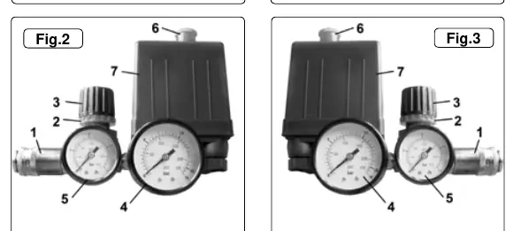
- Fig 1, 2, 3: Overview of the three models showing the main unit, handle, and tank configurations.
- Fig 2 & 3 (2/3): Pressure regulator locking ring used to secure the output pressure setting.
- Fig 2 & 3 (4/5): Gauges indicating main tank pressure and regulated output pressure.
- Fig 2 & 3 (6): On/Off switch for controlling the compressor power.
- Fig 2 & 3 (7): Pressure switch assembly which manages automatic motor start/stop cycles.
Model compatibility
- Requires a 13 Amp fused supply.
- Not suitable for outdoor use or in damp/wet locations.
- Air tools must be compatible with the compressor's output capacity.

Manual page author
Emily Carter
User documentation editor
Prepares concise manual descriptions and highlights the most useful setup, operation, and maintenance information for readers.