Documents / Warranty Safety
Sealey RoadStart 12V Emergency 8-Cylinder Jump Starter 5L RS103B.V2 Parts Guide
Quick reference guide for the Sealey RoadStart 12V Emergency Jump Starter (Model RS103B.V2). Includes a detailed parts breakdown, component identification, and essential maintenance information.
Table of contents
Quick guide from the manual
This document serves as the official parts information for the Sealey RoadStart 12V Emergency 8-Cylinder Jump Starter (Model RS103B.V2). It provides a visual breakdown of the unit's internal and external components to assist with identification and maintenance.
Device components
The unit consists of the following primary parts:
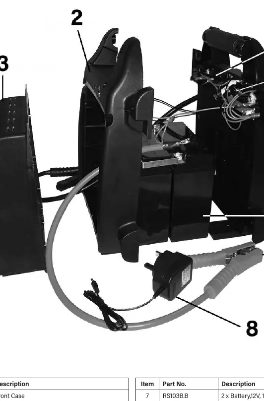
- Front and Back Case: The main housing (Items 1 & 2).
- Battery System: 2 x 12V, 19Ah/228Wh Lead Acid batteries (Item 7).
- Control and Power: Rotary On/Off switch (Item 4) and PCB circuit board (Item 6).
- Safety: Fuse box (Item 9) and internal fuse (Item --).
- Accessories: Positive and negative clamp assembly (Item 5) and UK mains charger (Item 8).
Maintenance and safety
Please note the following important conditions regarding the maintenance of your jump starter:
- Competent repair: Spare parts must be fitted by a competent person to ensure safety and functionality.
- Warranty: The product is covered by a 12-month guarantee from the date of purchase. Proof of purchase is required for any claims.
- Modifications: Sealey reserves the right to alter specifications and component parts without prior notice.
Contact information
For support or inquiries, you can contact Sealey Group:
Tel: 01284 757500Email: [email protected]: www.sealey.co.uk
Official resources from the manual
Manufacturer information
Sealey Group
Practical help
Common problems
Unit fails to operate
Check the internal fuse (RS105B-V2-FUSE) and ensure the battery (RS103B.B) is properly charged using the provided mains charger.
Before use
- Verify the model number is RS103B.V2.
- Inspect the clamp assembly for any signs of wear or damage.
- Ensure the mains charger is the correct 15V DC 0.8A type.
- Confirm the unit has been charged according to standard operating procedures.
Images and diagrams
- The diagram provides an exploded view of the RS103B.V2 unit, labeling the front and back cases, the internal PCB, the fuse box, and the battery configuration.
Model compatibility
- Spare parts are specific to the RS103B.V2 model; ensure compatibility before ordering replacements.

Manual page author
Michael Turner
Technical manual editor
Reviews PDF manuals for structure, safety notes, and practical product details so readers can find the right information quickly.