Tools / Pressure Washers
User Manual for Sealey START Series Starter/Chargers
Comprehensive user guide for Sealey START series starter/chargers (START320, START420, START560.V2, START660). Includes assembly instructions, battery preparation, charging procedures, jump-starting, and safety guidelines.
Table of contents
Manual images
Click an image to enlargeQuick Guide from the Manual
The Sealey START series units are heavy-duty starter/chargers designed for professional use. Before operation, ensure the charger voltage (12V or 24V) matches the battery voltage. Always inspect cables and connectors for wear before use. The unit must be connected to a suitable power supply (16A or 32A depending on the model) and must be properly earthed.
Assembly
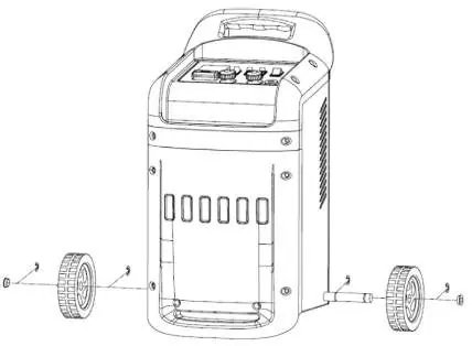
To assemble the unit, slide the axle through the casing at the bottom rear corner. Slide a wheel onto each end of the axle and secure them using the provided circlips.
Preparation
Before charging, ensure the battery capacity is compatible with the charger output. If the battery is removable, take it to a safe area. Remove electrolyte caps to allow gases to escape and check fluid levels; add distilled water if necessary to cover plates by 5-10mm. Do not touch battery fluid as it is corrosive.
Connecting Charger to Battery
For dual voltage chargers, set the voltage to match the battery (12V or 24V) by connecting the positive clamp to the appropriate terminal. Ensure clamps and terminals are clean. Connect the POSITIVE (Red) lead to the POSITIVE (+) terminal first, then the NEGATIVE (Black) lead to the NEGATIVE (-) terminal.
Charging the Battery
Connect the charger to the mains power supply. Set the mode switch to the 'charge' function. Select the charging rate (LOW, MEDIUM, or HIGH) according to the model. For START560.V2 and START660, use the rotary switch to select levels 1-6. Monitor the ammeter on the front panel; a high rate will slowly decrease as the battery charges. If the ammeter shows a low output, the battery may be fully charged.
Rapid Charging (START560.V2 and START660)
These models feature a fast-charge timer. Turn the timer to the required time (up to 60 minutes) and set the charging level to 4, 5, or 6. The current will automatically switch off when the time elapses.
Starting (Jump Start)
Ensure the battery is connected to the vehicle. Set the output voltage to match the vehicle battery. Connect the charger as described in the connection section. Set the switch to the 'START' position. Turn the vehicle ignition on and crank the engine for a MAXIMUM of 3 seconds. If it does not start, wait 120 seconds before trying again (maximum 5 cycles).
Fuse Replacement
The unit is equipped with a safety fuse. If it blows, turn off and disconnect from the mains. Allow the unit to cool, identify the cause (overload, short circuit, or prolonged starting), and replace the fuse under the fuse cover on the control panel. Do not use a copper bridge or incorrect fuse type.
Manufacturer information
Sealey Group
Practical help
Common problems
Fuse blows
Caused by overload, short circuit, or prolonged starting attempts. Disconnect, identify the cause, and replace with an identical fuse.
Vehicle will not start
Do not continue cranking as this may damage the vehicle battery and electrical circuits. Disconnect and investigate for vehicle faults.
Ammeter shows low output
If the charger is connected to a fully charged battery, the ammeter will show a low output; no charging is necessary.
Before use
- Inspect power cables, plugs, and connectors for wear or damage.
- Ensure the charger voltage (12V/24V) matches the battery voltage.
- Check that the charger is placed on a stable, upright surface.
- Ensure battery terminals are clean and free from oxidation.
- Verify the power supply (16A or 32A) is adequate for the model.
Specs in practice
- Output 12/24V
- Selectable voltage output to match the specific battery being charged.
- Charging rates
- Adjustable settings to control the speed and intensity of the charge.
- Polarity protection
- Fuse-based protection to prevent damage from short circuits or incorrect connections.
Images and diagrams
- Fig 1: Assembly of wheels and axle to the charger base.
- Fig 4: Connection diagram for a single battery.
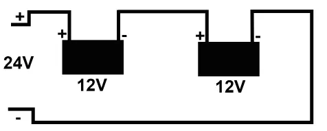
- Fig 5: Connection diagram for two 12V batteries connected in series.
Model compatibility
- START560.V2 and START660 include a fast-charge timer function.
- Requires 16A or 32A supply depending on the specific model.

Manual page author
Emily Carter
User documentation editor
Prepares concise manual descriptions and highlights the most useful setup, operation, and maintenance information for readers.