Power / Solar Inverters
Quick Installation Guide for Segensolar H3 5-12kW Three Phase Storage Inverter
A concise installation and setup guide for the Segensolar H3 5-12kW Three Phase Storage Inverter. Includes mounting instructions, grid and EPS wiring diagrams, meter connection, start-up procedures, and WiFi configuration.
Table of contents
Quick guide from the manual
This document provides essential installation and configuration steps for the Segensolar H3 5-12kW Three Phase Storage Inverter. It covers physical mounting, electrical wiring for grid, EPS, PV, battery, and meter connections, as well as system start-up and WiFi setup.
Mounting
Ensure the inverter is installed with proper clearance (500mm on all sides). Drill 6 holes using an 8mm drill bit to a depth of at least 50mm. Secure the wall bracket with expansion bolts, mount the inverter, and lock the side screws to ensure it is firmly attached.
Electrical Connections
Grid Connection: Use a 5-core cable with a diameter of 9-16mm. Separate the connector, insert the cable, connect according to polarity, and tighten. Ensure a click sound when connecting to the inverter.
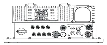
EPS Connection: Follow local wiring regulations. For some regions (e.g., Australia, New Zealand), the N cables of the Grid and EPS sides must be connected together for the EPS function to work.
PV Connection (H3 Only): Use 12 AWG wire. Strip 6mm of insulation. Ensure proper polarity when inserting into the PV connector.
Battery Connection: Connect the power line and communication cable between the BMS and the inverter. Ensure the grounding cable is connected.
Meter Connection: Insert L1/L2/L3/N wires and RS485A/B cables into the meter. Ensure the CT arrow faces the grid. Connect RS485A to pin 4 and RS485B to pin 3 of the inverter's METER/RS485 port.
Inverter Start-Up
- Ensure the inverter is fixed securely.
- Verify that GRID, EPS, PV, and Battery wirings are completed.
- Ensure BMS buttons and battery switch are ON.
- Turn on the PV/DC switch, AC breaker, EPS breaker, and battery breaker.
- If the main page shows "switch off", long-press the '√' button to go to the START/STOP page and set it to start.
- Check the country code and set the time via the inverter button or the App.
WiFi Stick Installation
Plug the Smart WiFi stick into the WiFi/GPRS port on the underside of the inverter. Use the FoxCloud App to configure the network. Scan the QR code on the stick, connect your mobile device to the Smart WiFi (SSID: W-xxxxx, Password: mtmt2020), and follow the in-app instructions to connect to your home router.
Firmware Update
Prepare a PC and a USB 2.0 disk (FAT16 or FAT32 format, less than 32GB). Extract update files into the USB disk. Unscrew the waterproof lid, insert the USB disk, and use the LCD menu to select the upgrade file and confirm.
Practical help
Common problems
sw bus volt fault reported in off-grid mode
Check the troubleshooting section on page 55 of the full manual.
EPS function not working
Ensure the N cables of the Grid and EPS sides are connected together (required for specific regional safety regulations).
Inverter not starting
Verify that all breakers (PV/DC, AC, EPS, Battery) are turned ON and the BMS is active.
Before use
- Verify wall strength and drill 6 holes (8mm diameter, 50mm depth).
- Prepare 5-core AC cable (9-16mm diameter).
- Ensure battery communication cable is connected to the inverter.
- Check that the CT meter arrow points towards the grid.
- Ensure the country code is set correctly during the first start-up.
Images and diagrams
- Wiring diagrams are provided for Grid, EPS, PV, Battery, and Meter connections.
- Specific wiring instructions for CT-to-CT meter connections are included.
- Parallel operation wiring diagrams are available for multi-unit setups.
Model compatibility
- H3/AC3 is a 3L-N-PE system; N line is mandatory.
- USB port supports USB 2.0 only; do not use USB 3.0 disks.
- CT meter is not included in the package and must be purchased separately if required.

Manual page author
Michael Turner
Technical manual editor
Reviews PDF manuals for structure, safety notes, and practical product details so readers can find the right information quickly.