Industrial / Process Controllers
Installation Instructions for Siemens Outside Air Sensor 536-778
Quick installation guide for the Siemens Outside Air Sensor (100K Ohm Thermistor). Includes step-by-step instructions for Option A and Option B mounting, wiring diagrams, and installation prerequisites.
Table of contents
Manual images
Click an image to enlargeQuick guide from the manual
The Siemens Outside Air Sensor (Model 536-778) is designed to provide temperature input to a controller. The installation method depends on the distance between the utility mounting box and the outlet end of the pulling elbow:
- Option A: Use if the distance is less than 22 inches (56 cm).
- Option B: Use if the distance is greater than 22 inches (56 cm).
Prerequisites: The preferred location is the north side of the building in the shade, protected from direct sunlight and exhaust drafts. Ensure all wiring complies with the National Electrical Code (NEC) and local regulations.
Required Tools
- Power screwdriver with standard screw chuck or medium flat-blade screwdriver
- Wire cutter/stripper
- Drill and drill bits
Option A Installation
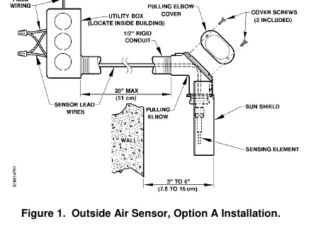
- Use an existing opening or drill an opening through the outside wall for 1/2-inch (13 mm) rigid conduit. The sensor must be located three to six inches (7.5 to 15 cm) from the wall.
- Feed the sensor leads through the rigid conduit to the utility box inside the building. Thread the sensor onto the rigid conduit.
- Rotate the sensor so that the shield points down to shade the sensing element from direct and indirect sunlight.
- Connect the sensor leads to the field wiring inside the utility box.
- Connect the field wiring to the controller as shown in the wiring diagram.
Option B Installation
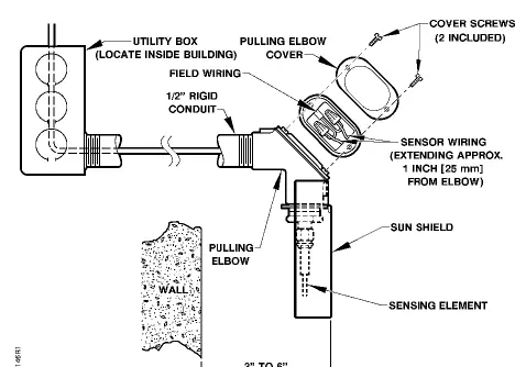
- Drill an opening through the outside wall for 1/2-inch (13 mm) rigid conduit. The sensor must be located three to six inches (7.5 to 15 cm) from the wall.
- Remove the pulling elbow cover and gasket.
- Pull the sensor lead wires from the pulling elbow and thread the pulling elbow/sensor assembly onto the conduit.
- Rotate the sensor so that the shield points down to shade the sensing element.
- Cut off excess sensor wire leads approximately one inch (25 mm) from the pulling elbow and strip 3/8-inch (9.5 mm) of insulation.
- Pull the field wiring to the pulling elbow and connect it to the sensor wiring.
- Replace the pulling elbow cover and gasket, ensuring the gasket seals the elbow.
- Connect the field wiring at the controller as shown in the wiring diagram.
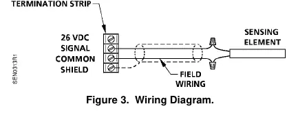
Wiring
Refer to the wiring diagram for connection details. Some Siemens Building Technologies controllers may require a shield termination. For individual panel wiring details, refer to the appropriate hardware manual.
Manufacturer information
Siemens AG
Practical help
Common problems
Sensor reading inaccuracies
Ensure the sensor shield points down to protect the sensing element from direct and indirect sunlight.
Wiring distance constraints
Choose the installation method based on the distance between the utility box and the pulling elbow: Option A for 22 inches.
Before use
- Verify the north side of the building is chosen for installation.
- Ensure the sensor is protected from direct sunlight and exhaust drafts.
- Check that the wiring run length is within limits for the controller.
- Have a power screwdriver, wire cutter/stripper, and drill ready.
- Ensure all wiring complies with NEC and local regulations.
Specs in practice
- 100K Ohm Thermistor
- The sensor resistance type used for temperature input.
- 0°F to 120°F (-18°C to 49°C)
- The operating temperature range of the sensor.
Images and diagrams
- Figure 1: Shows Option A installation with rigid conduit and utility box.
- Figure 2: Shows Option B installation with pulling elbow and sensor wiring.
- Figure 3: Wiring diagram showing 26 VDC signal, common, and shield connections.
Model compatibility
- Some Siemens Building Technologies controllers may require a shield termination.
- Refer to the appropriate hardware manual for individual panel wiring details.

Manual page author
Emily Carter
User documentation editor
Prepares concise manual descriptions and highlights the most useful setup, operation, and maintenance information for readers.