Industrial / Communication Modules
Equipment Manual for Siemens SIMATIC ET 200MP IM 155-5 PN HF Interface Module
Comprehensive equipment manual for the Siemens SIMATIC ET 200MP IM 155-5 PN HF interface module. Includes wiring diagrams, configuration control, diagnostic procedures, and technical specifications.
Quick answers from the manual
Quick answer
- The IM 155-5 PN HF is an interface module for the SIMATIC ET 200MP distributed I/O system, connecting it to PROFINET IO. It supports advanced features like configuration control, isochronous mode, and system redundancy. p. 11, 12, 14
Key actions
- Wiring the 24V DC supply p. 21
- Configuring via STEP 7 p. 25, 27
Problems and fixes
ERROR LED flashing
Evaluate the diagnostics and correct the error; check configuration.
p. 38Error codes
| Code | Meaning | Action | Pages |
|---|---|---|---|
| 80B1H | Invalid length | Check control data record length. | p. 28 |
| 80B5H | Configuration control not configured | Enable configuration control in parameters. | p. 28 |
Technical specifications
| Parameter | Value | Meaning | Pages |
|---|---|---|---|
| Supply voltage | 24 V DC | Rated value | p. 52 |
| Max. I/O data | 512 bytes | Per station | p. 12 |
Where to find it in the PDF
- Product overview p. 11
- Technical specifications p. 52
Table of contents
Manual images
Click an image to enlargeQuick guide from the manual
This manual provides essential information for the installation, configuration, and operation of the Siemens SIMATIC ET 200MP IM 155-5 PN HF interface module. Key tasks include connecting the 24V DC supply, establishing PROFINET communication, and configuring the module using STEP 7 software.
Product overview
The IM 155-5 PN HF interface module connects the ET 200MP distributed I/O system with PROFINET IO. It supports features such as isochronous real-time communication (IRT), media redundancy (MRP), and configuration control for flexible system setups.
Wiring
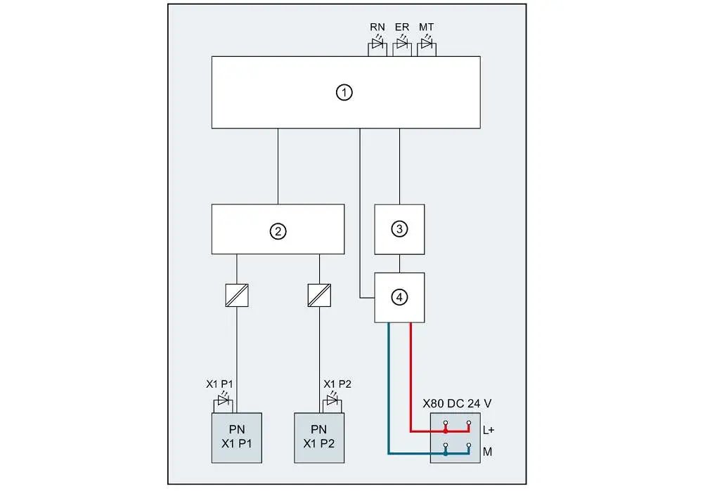
The module requires a 24V DC supply connected to the X80 terminal. PROFINET communication is established via RJ45 connectors. Ensure proper pin assignment as detailed in the manual to avoid connection errors.
Configuration control
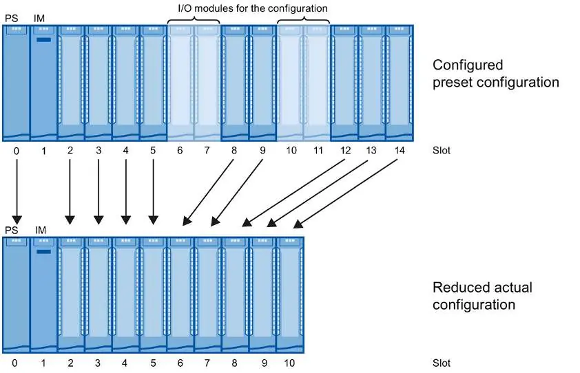
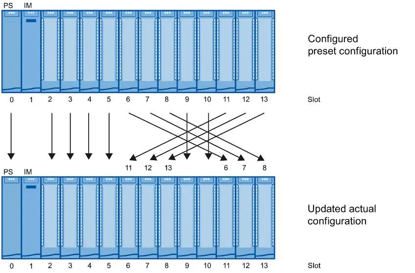
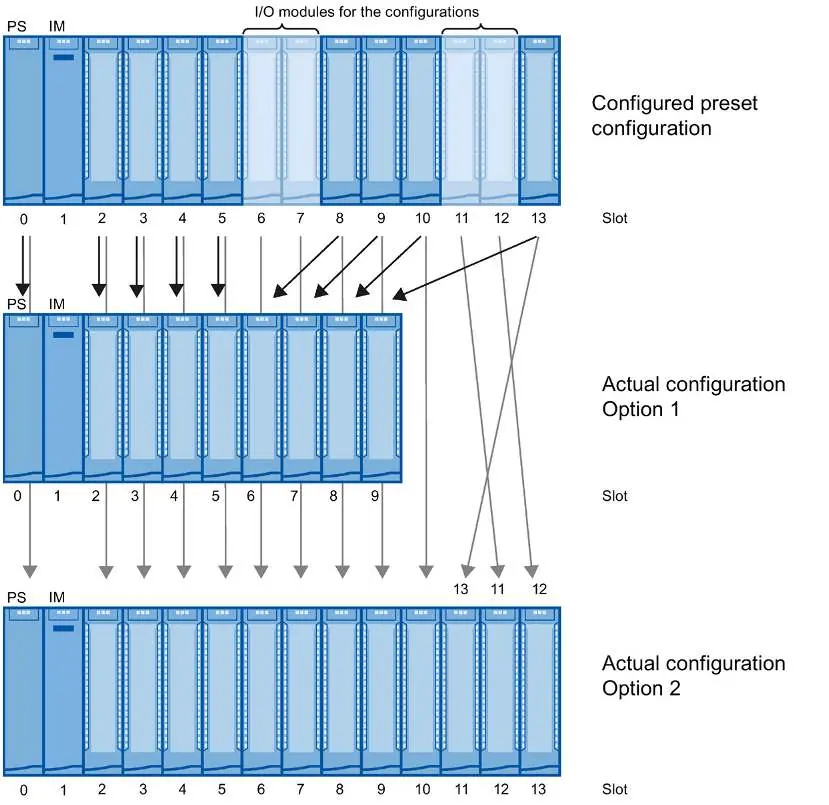
Configuration control allows you to prepare your distributed I/O system for future extensions. By using control data record 196, you can configure the planned maximum configuration in advance and vary it later. The manual provides detailed procedures for configuring without empty slots, extending configurations, and combining different configurations.
Status and error displays
The module features LED indicators for quick diagnostics:
- RUN (green): Indicates the module status (e.g., starting up, exchanging data).
- ERROR (red): Indicates group errors or configuration issues.
- MAINT (yellow): Indicates maintenance requirements.
If an error occurs, evaluate the diagnostics buffer in the CPU or the module status in STEP 7.
Technical specifications
The module operates on 24V DC. It supports up to 30 modules downstream from the interface module. Detailed specifications regarding power consumption, address areas, and environmental conditions are provided in the technical data section.
Manufacturer information
Siemens AG
Practical help
Common problems
Module not starting
Check if the 24V DC supply voltage is present and within the permissible range (20.4V - 28.8V).
Communication failure
Verify the PROFINET cable connection and ensure the IO controller is configured correctly.
Configuration error
Verify the control data record 196 and ensure the actual configuration matches the preset configuration.
Before use
- Verify 24V DC supply voltage
- Check PROFINET cable connections
- Ensure correct module slot assignment
- Configure the module in STEP 7
- Check for firmware updates
Specs in practice
- Supply voltage
- 24 V DC (SELV/PELV)
Images and diagrams
- Block diagram illustrates the internal electronics, PROFINET switch, and power supply connections.
- Configuration diagrams show how to map configured slots to real slots for flexible system setups.
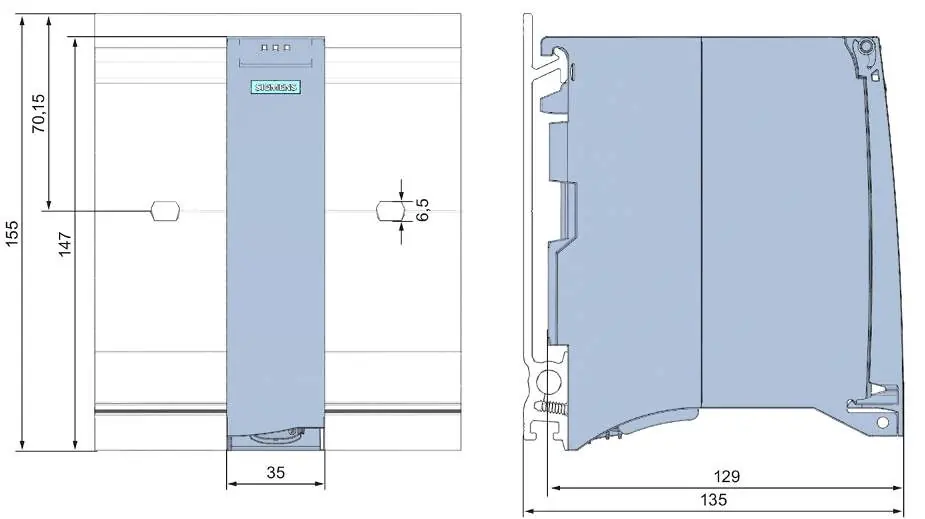
- Dimension drawings provide necessary clearance measurements for cabinet installation.
Model compatibility
- Requires STEP 7 (TIA Portal) V13 or higher for full functionality.
- Supports system redundancy S2 on S7-400H and S7-1500R/H CPUs.

Manual page author
Emily Carter
User documentation editor
Prepares concise manual descriptions and highlights the most useful setup, operation, and maintenance information for readers.