Industrial / Programmable Logic Controllers
SIMATIC ET 200SP BaseUnits Device Manual
Comprehensive device manual for Siemens SIMATIC ET 200SP BaseUnits. Includes technical specifications, connection diagrams, and installation guidelines for various BaseUnit types and potential distribution modules.
Quick answers from the manual
Quick answer
- This manual provides technical specifications, connection diagrams, and installation instructions for the SIMATIC ET 200SP BaseUnits and potential distribution modules. p. 1, 6, 7, 8
Key actions
- Connecting the BaseUnit p. 25, 29, 32, 36
Problems and fixes
Internal fuse triggered
Replace the terminal box if the internal, non-replaceable fuse is triggered.
p. 39, 43, 46, 50Technical specifications
| Parameter | Value | Meaning | Pages |
|---|---|---|---|
| Max. current (process terminals) | 2A to 10A | Maximum current capacity per terminal depending on the specific BaseUnit model. | p. 26, 30, 33, 37 |
Where to find it in the PDF
- BaseUnits for peripheral modules p. 23, 85
- BaseUnits for motor starters p. 86, 119
- Potential distribution modules p. 120, 142
Table of contents
Manual images
Click an image to enlargeQuick Guide
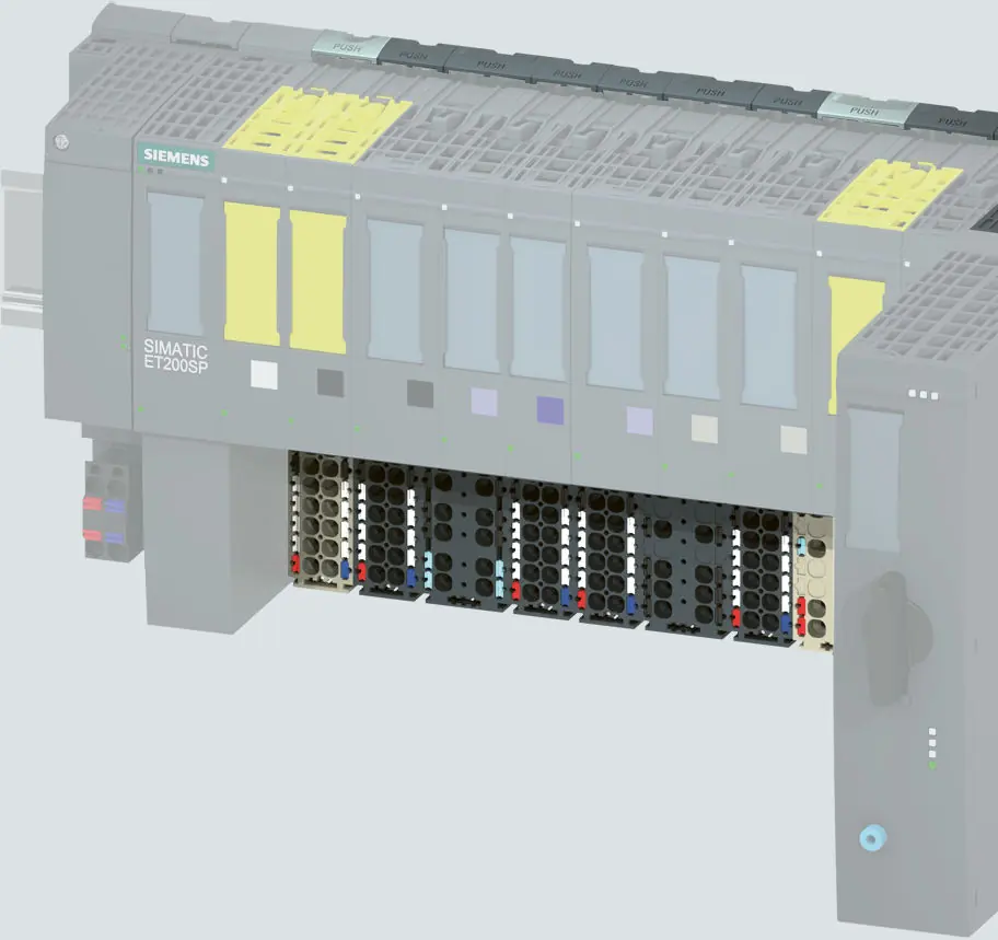
This manual provides technical specifications, connection diagrams, and installation instructions for the SIMATIC ET 200SP BaseUnits and potential distribution modules. These units are designed for the decentralized peripheral system ET 200SP, offering robust and service-friendly assembly with standing wiring.
Product Overview
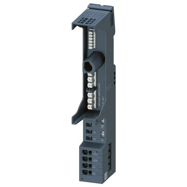
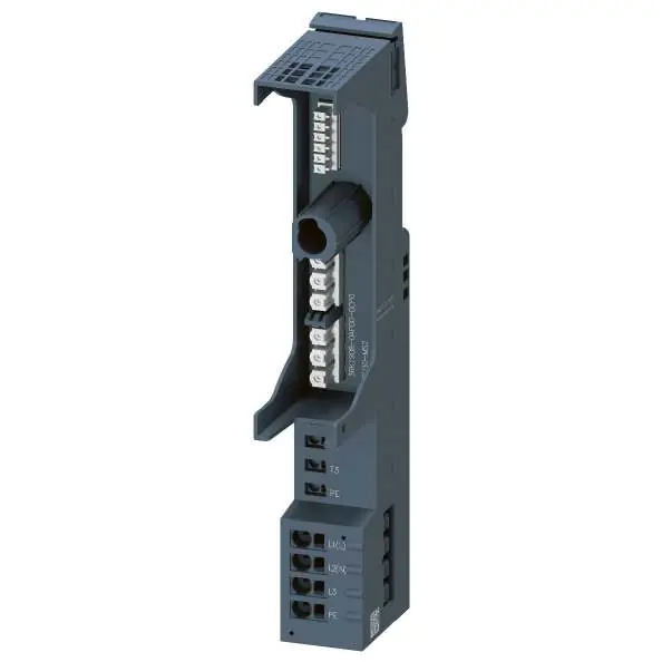
The ET 200SP system includes various BaseUnits (BU) that define the process connection, pluggable peripheral module/motor starter, and supply voltage feed. The properties of each BaseUnit can be identified by its short designation.

Installation and Connection
BaseUnits can be placed at any position within the ET 200SP system. The push-in connection technology allows for tool-free wiring. Important: All BaseUnits placed in a potential group must correspond to the supply potential of the associated light-colored BaseUnit.


- Potential Groups: Light-colored BaseUnits open a new potential group, while dark-colored BaseUnits continue the potential group from the left.
- Wiring: Connection details vary by BaseUnit type. Always refer to the specific connection diagram for the module in use.
- Safety: Ensure the supply voltage matches the nominal voltage of the peripheral modules in the potential group.
Potential Distribution Modules
PotDis modules consist of a potential distribution BaseUnit (PotDis-BU) and a terminal block (PotDis-TB). These allow for system-integrated potential distribution. Note that PotDis-BUs are only permitted for SELV/PELV potentials.
Technical Data
Technical specifications, including supply voltage, current carrying capacity, and environmental conditions, are provided for each specific BaseUnit type (A0, A1, B0, B1, C0, C1, D0, F0, U0) and motor starter BaseUnit (BU30-MS1 to BU30-MS10) in their respective chapters.
Manufacturer information
Siemens AG
Practical help
Common problems
Internal fuse triggered
If a different peripheral module is used, an internal, non-replaceable fuse may trigger. The terminal box must be replaced.
Voltage mismatch
Ensure the connected supply voltage matches the nominal voltage of the potential group.
Before use
- Verify the BaseUnit type matches the peripheral module.
- Check the supply voltage requirements.
- Ensure the potential group configuration is correct.
- Verify the wiring diagram for the specific BaseUnit type.
Specs in practice
- Push-In connection
- Tool-free wiring technology.
- Potential group
- Group of modules sharing the same supply potential.
- AUX terminal
- Additional terminals for protective conductor or potential connection.
Images and diagrams
- Schematic diagrams show the internal connections of the BaseUnits, including the backplane bus, potential rails (P1, P2), and AUX rails.
Model compatibility
- Light-colored BaseUnits open a new potential group.
- Dark-colored BaseUnits continue the potential group from the left.
- PotDis-BUs are only permitted for SELV/PELV potentials.

Manual page author
David Miller
Documentation analyst
Organizes user manual content into clear summaries, with attention to model details, product context, and everyday usability.