Power / Transformers & Supplies
Installation Guide for SloanLED 100L1 24 VDC Power Supply
Quick installation guide for the SloanLED 100L1 24 VDC Power Supply. Includes mounting instructions, electrical connection requirements, safety spacing, and troubleshooting steps.
Table of contents
Manual images
Click an image to enlargeQuick guide from the manual
This document provides essential installation and safety instructions for the SloanLED 100L1 24 VDC Power Supply. Proper installation is critical for safety and product longevity. Ensure all electrical work is performed by a licensed electrician and complies with local codes.
Tools and supplies required
Before beginning the installation, ensure you have the following items:
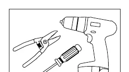
- Tools: Wire strippers, drill, and screwdriver.
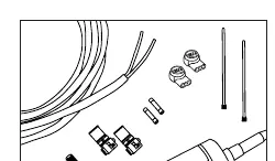
- Supplies: Conduit and electrical enclosure (if not placed in a sign made from enclosure-rated material), #8 pan head screws (M4 for Europe), UL Listed PLTC cable, UL Listed electrical wire connectors (e.g., wirenuts), and silicone.
Installation and mounting
Follow these steps to mount the power supply:
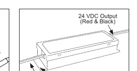
- Identify components: Locate the primary wires (Black & White), secondary wires (Red & Black), and the mounting tabs on the power supply.
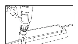
- Mounting: Use the mounting tabs in the corners to secure the power supply to the enclosure.
- Ventilation and spacing: Ensure adequate ventilation. The operating ambient temperature must be between -40°C and 55°C.
- Clearance requirements: Maintain a minimum spacing of 1 inch (25 mm) from thermoplastic, wood, fiber, or other combustible enclosure materials.
- Adjacent units: If mounting multiple power supplies, do not mount them closer than 1 inch (25 mm) end-to-end or 4 inches (102 mm) side-to-side.
Electrical connections
Caution: Have a licensed electrician connect the primary side.
- Primary: Connect the primary wires (Black & White) according to local electrical codes.
- Secondary: The output is 24 VDC (Red & Black). Ensure all secondary connections are Red-to-Red and Black-to-Black.
- Load: Verify that the output current is less than 4.15 DC Amps to prevent overloading.
Troubleshooting
If the sign is not functioning properly, check the following:
- Ensure primary voltage is between 120-277 VAC.
- Verify secondary voltage is 24 VDC.
- Confirm output current is 4.15 Amps or less.
- Check that the power supply is not overloaded.
- Ensure there are no shorts in the secondary wiring.
- Verify all secondary connections are correct (Red-to-Red and Black-to-Black).
Practical help
Common problems
Sign not functioning
Check that primary voltage is 120-277 VAC, secondary voltage is 24 VDC, and output current is 4.15 Amps or less.
Wiring issues
Ensure there are no shorts in the secondary wiring and that connections are Red-to-Red and Black-to-Black.
Overheating or failure
Verify the power supply is not overloaded and that it has adequate ventilation (1 inch spacing from combustibles).
Before use
- Verify primary voltage is 120-277 VAC.
- Ensure the enclosure is made from enclosure-rated material.
- Check that output current is 4.15 Amps or less.
- Confirm ambient temperature is between -40°C and 55°C.
- Ensure adequate ventilation space is provided.
- Verify all tools (wire strippers, drill, screwdriver) are available.
Specs in practice
- Primary Voltage
- 120-277 VAC input range.
- Secondary Voltage
- 24 VDC output.
- Max Output Current
- 4.15 Amps.
- Operating Temperature
- -40°C to 55°C.
Images and diagrams
- The wiring diagram identifies primary wires (Black & White) and secondary wires (Red & Black).
- The mounting diagram illustrates using the corner tabs to secure the unit.
Model compatibility
- Requires UL Listed PLTC cable and UL Listed wire connectors.
- If mounted inside a sign cabinet, the cabinet must be made from enclosure-rated material.
- Europe installation requires M4 pan head screws and 3M Scotchlok connectors.

Manual page author
Michael Turner
Technical manual editor
Reviews PDF manuals for structure, safety notes, and practical product details so readers can find the right information quickly.