Power / Transformers & Supplies
Comelit 1210A System Power Supply Unit User Manual
Quick guide for the Comelit 1210A system power supply unit. Includes installation instructions, wiring diagrams, technical specifications, and safety precautions for Simplebus2 systems.
Table of contents
Manual images
Click an image to enlargeImportant Information
The Comelit 1210A is a dedicated system power supply unit designed specifically for Simplebus2 installations. This device is intended for indoor use only and must be installed within a closed electrical panel to ensure access is restricted to authorized personnel. Proper installation requires an upstream omnipolar switch with a contact opening of at least 3 mm.
Safety Precautions
- Disconnect the power supply before performing any wiring or maintenance operations.
- Ensure terminal protections are replaced after installation.
- Do not obstruct ventilation slots or cooling apertures to prevent overheating.
- The device should be installed in a location that prevents unauthorized access.
- Adding a mains filter is recommended to protect the system from electrical disturbances.
Installation
The device is designed for DIN rail mounting (occupies 8 DIN modules). Ensure the installation environment is dry and protected. An appropriate omnipolar switch must be installed upstream of the video entry phone system to allow for safe disconnection.
Wiring
The terminal connections are as follows:
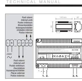
- L N: Mains power input (230V AC).
- L1 L1: Bus line for external units (34V DC).
- L2 L2: Bus line for internal units (34V DC).
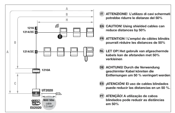
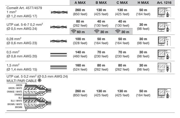
Note: Using shielded cables may reduce the maximum operating distances by up to 50%. Refer to the cable distance table for specific limitations based on cable type and cross-section.
Troubleshooting
If the device stops working due to a short circuit, it must be reset. To reset the operation, disconnect the mains voltage for approximately 5 minutes before reconnecting.
Technical Specifications
- Power Supply Voltage: 230V AC, 50-60 Hz
- Output Voltage: 34V DC
- Max Current Delivered: 1A
- Max Power Delivered: 34W
- Operating Temperature: 0 to 40 degrees Celsius
- DIN Modules: 8
Manufacturer information
Comelit Group S.p.A.
Practical help
Common problems
Device stops working after a short circuit
Cut the mains voltage for about 5 minutes to reset the device.
Reduced operating distance
Using shielded cables can reduce the maximum distance by 50%. Check cable type and length requirements.
Before use
- Ensure the installation location is a closed electrical panel.
- Verify that an omnipolar switch with at least 3mm contact opening is installed upstream.
- Confirm mains power is 230V AC.
- Ensure ventilation slots are not obstructed.
- Verify that terminal protections are in place.
Specs in practice
- Input Voltage
- 230V AC, 50-60 Hz mains power.
- Output Voltage
- 34V DC for Simplebus2 system components.
Images and diagrams
- L N terminals are for the 230V mains power input.
- L1 L1 terminals connect to the external unit bus line.
- L2 L2 terminals connect to the internal unit bus line.
Model compatibility
- Designed exclusively for Comelit Simplebus2 systems.

Manual page author
Michael Turner
Technical manual editor
Reviews PDF manuals for structure, safety notes, and practical product details so readers can find the right information quickly.