Lighting / Fixtures
SloanLED VL5 12V LED Signage Module
Comprehensive installation and wiring guide for SloanLED VL5 12V LED modules. Includes step-by-step instructions for new installations and retrofits, wiring diagrams, power supply capacity charts, and troubleshooting procedures.
Table of contents
Manual images
Click an image to enlargeQuick Guide
The SloanLED VL5 12V LED module is designed for signage illumination. This guide covers both new installations and retrofits. Important: Installation must be performed by a qualified electrician in accordance with local and national electrical codes. The product is not suitable for submersion or direct exposure to water.
New Installation
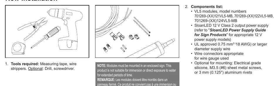
- Tools Required: Measuring tape, wire strippers. Optional: Drill, screwdriver.
- Components: Ensure you have VL5 modules, a SloanLED 12V Class 2 output power supply, UL approved 0.75 mm² (18 AWG) or larger supply wire, and appropriate wire connectors.
- Layout: Refer to VL5 density guidelines and the power supply loading chart to determine the number of modules and power supplies needed.
- Peel and Stick: Clean the inside of the sign with rubbing alcohol and allow it to dry. Remove the tape backing and stick modules into place. Ensure they are firmly attached.
- Fasteners: If desired, modules can be secured with #6 (3.5 mm) pan head sheet metal screws.
Retrofit Instructions
- Identify the sign to be retrofitted and ensure the branch circuit is within the voltage range for the LED power supply.
- Remove existing lighting equipment (neon, fluorescent, ballasts, transformers). Dispose of materials according to local laws.
- Install a new disconnect switch if required by code.
- Check the structural integrity of the sign. Repair and seal any unused openings in the electrical enclosure. Openings larger than 0.5" (12.7 mm) require a metal patch secured by screws or rivets and caulked with non-hardening caulk.
- Clean the inside of the sign with a non-oil based cleaner and ensure it is dry.
- Follow the "New Installation" steps to populate the sign with LED modules.
- Connect modules to the power supply and install a disconnect switch if required.
Wiring and Connections
Modules may be connected in series or parallel. It is recommended to connect no more than half of the maximum 60 W power supply capacity in series to minimize line loss.
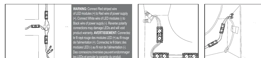
- Polarity: Connect the Red striped wire of the LED modules (+) to the Red wire of the power supply (+). Connect the White wire of the LED modules (-) to the Black wire of the power supply (-).
- Warning: Reverse polarity connections may damage LEDs and will void the product warranty.
- Unused Wires: Cap all unused wires. Do not loop the strand of modules to create a closed circuit.
Troubleshooting
- Entire sign does not light: Check the connection from the power supply lead to the first module. Verify polarity (Red-to-Red, Black-to-White).
- Still does not light: Check the output voltage of the power supply using a voltmeter. It should be DC 12.0 V ± 0.5 V. If there is no output, check the input voltage or try a different power supply.
- Still does not light (secondary): If the power supply has input power but modules do not light, check for a short in the secondary wiring.
- Intermittent lighting: This is typically caused by a bad connection or reverse polarity between the modules that light and those that do not.
Power Supply Capacity
Refer to the "12 VDC Power Supply Capacity Chart" in the manual to determine the maximum number of modules supported by your power supply (20W, 30W, 60W, 150W, 100W). Capacities are based on 90% of the power supply output. For North American installations, use only UL Listed or Recognized Class 2 power supplies.
Practical help
Common problems
Entire sign or leg does not light
Check connection from power supply to first module. Verify polarity (Red-to-Red, Black-to-White).
No output voltage from power supply
Check input voltage to the power supply. If input is correct but no output, replace the power supply.
Intermittent lighting or partial failure
Check for bad connections or reverse polarity between the working and non-working modules.
Before use
- Verify you have a 12V Class 2 power supply.
- Ensure wire gauge is 0.75 mm² (18 AWG) or larger.
- Clean sign interior with rubbing alcohol.
- Ensure sign interior is completely dry.
- Confirm power supply capacity matches the number of modules.
Specs in practice
- Class 2 Power Supply
- Safety standard required for the power source in North American installations.
- Reverse Polarity
- Connecting Red to Black; will damage LEDs and void warranty.
Images and diagrams
- Wiring Diagram: Shows correct connection of Red striped wire to Red (+) and White wire to Black (-).
- Layout: Illustrates measuring can depth and stroke width for proper module placement.
Model compatibility
- Not suitable for submersion or direct water exposure.
- Must be mounted in an enclosed sign.
- For North American installations, use UL Listed/Recognized Class 2 power supplies only.

Manual page author
Emily Carter
User documentation editor
Prepares concise manual descriptions and highlights the most useful setup, operation, and maintenance information for readers.