Lighting / LED Modules
SloanLED FlexTAPE LED Strip Installation Guide
A comprehensive installation guide for SloanLED FlexTAPE LED strips. Includes step-by-step instructions for cutting, mounting, wiring, and sealing, along with power supply capacity charts and troubleshooting procedures.
Table of contents
Manual images
Click an image to enlargeQuick guide from the manual
SloanLED FlexTAPE is a 12V LED lighting system designed for installation in enclosed sign cabinets or boxes. Key requirements include maintaining correct polarity (Red to +, Black to -), not exceeding a maximum series length of 16.4 ft (5 m) to prevent line loss, and ensuring all connections are protected from moisture using electrical grade non-corrosive silicone.
Tools and supplies
Required items include a measuring tape, scissors or shears. Optional but recommended items include PLTC cable, utility knife, SloanLED approved neutral cure sealant, soldering iron, SloanLED FlexTAPE connectors, and silicone end caps.
Installation steps
- Clean surface: Clean the inside of the channel letter or mounting track with rubbing alcohol and allow it to dry.
- Cut to length: Cut the FlexTAPE to the desired length in approximate 2 inch (50 mm) segments.
- Peel and stick: Remove the tape backing and firmly attach the strip to the surface. Avoid pressing directly on LEDs or circuit components, especially around sharp corners.
Connections and wiring
Sections can be connected in series or parallel. Connections can be made via soldering or using SloanLED FlexTAPE connectors.
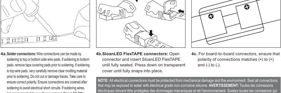
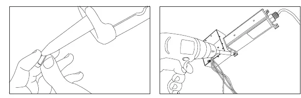
- Solder connections: Wire connections can be made to top or bottom wire pads. If soldering to bottom pads, remove tape covering. If soldering to top pads, carefully remove clear molding material. Ensure correct polarity and cover connections to prevent short circuits.
- Connectors: For board-to-wire or board-to-board connectors, ensure the polarity matches (+) to (+) and (-) to (-). Insert wires until fully seated and press down on the transparent cover until it snaps into place.
Sealing and protection
All electrical connections must be protected from mechanical damage and the environment. Seal all connections exposed to water with electrical grade non-corrosive silicone. Use SloanLED silicone end caps (P/N 402566 for ends with wires, 402566-NH for ends without) on cut ends for a reliable seal.
Power supply capacity
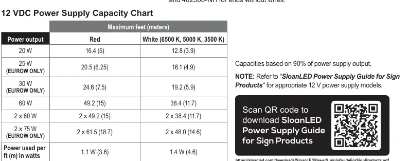
Capacities are based on 90% of power supply output. Refer to the 12 VDC Power Supply Capacity Chart in the manual to determine the maximum feet/meters allowed based on the power output (e.g., 60W power supply supports up to 49.2 ft (15 m) for Red, 38.4 ft (11.7 m) for White).
Troubleshooting
A licensed electrician should perform all troubleshooting steps.
- Entire leg does not light: Check connection from power supply lead to the first section. Verify polarity (Red to +, Black to -). Check output voltage of power supply (should be 12.0 VDC ± 0.5 VDC).
- Leg lights intermittently: Usually caused by a bad connection or reverse polarity between sections. Inspect for damage or cuts in the assembly.
- Leg is dim: Ensure the maximum length has not been exceeded. Check secondary voltage; if below 11.5 VDC, the power supply may be overloaded.
- One segment does not light: Replace the specific section with a new one.
Practical help
Common problems
Entire leg does not light
Check polarity (Red to +, Black to -) and verify power supply output is 12.0 VDC ± 0.5 VDC.
Leg lights intermittently
Check for bad connections or reverse polarity between sections. Inspect for physical damage or cuts.
Leg is dim
Verify maximum length has not been exceeded. Check secondary voltage; if below 11.5 VDC, the power supply is likely overloaded.
One segment does not light
Replace the faulty segment with a new one.
Before use
- Ensure power supply is 12V DC.
- Verify polarity: Red to (+), Black to (-).
- Check that total series length does not exceed 16.4 ft (5 m).
- Prepare silicone sealant for water-exposed connections.
- Ensure mounting surface is clean and dry.
Images and diagrams
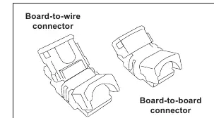
- Board-to-wire connector: Used for connecting power leads to the strip.
- Board-to-board connector: Used for joining two strips together.
- Solder pads: Alternative connection method requiring careful polarity matching.
Model compatibility
- Not suitable for immersion or direct water exposure without proper silicone sealing.
- Modules must be mounted in an enclosed sign cabinet or box.

Manual page author
David Miller
Documentation analyst
Organizes user manual content into clear summaries, with attention to model details, product context, and everyday usability.