Power / Solar Inverters
User Manual for SMA Sunny Highpower Peak3 Inverter
Quick reference guide for the SMA Sunny Highpower Peak3 series. Includes safety instructions, installation steps, electrical connection (AC/DC), commissioning, and user interface configuration.
Table of contents
Manual images
Click an image to enlargeImportant Information from the Manual
This document serves as a quick reference guide for the installation, commissioning, and operation of the SMA Sunny Highpower Peak3 inverter. It is intended for qualified personnel only. Always refer to the latest version of the comprehensive manual available at www.SMA-Solar.com for detailed configuration and decommissioning procedures.
Safety Instructions
Failure to observe safety instructions can result in death, serious injury, or property damage. Key safety measures include:
- Ground Faults: Disconnect the product from all voltage sources and ensure it cannot be reconnected before working on the device. Wait 5 minutes after disconnecting before touching any parts.
- Electrical Safety: Do not touch non-insulated parts or cables. Use only measuring devices with measurement ranges designed for the maximum AC and DC voltage of the inverter.
- Handling: Transport and lift the product carefully, taking its weight into account. Use provided carrying handles or a hoist.
- Environment: Only open the product if the ambient temperature is not below -5°C (23°F) and the environment is free of sand and dust.
Installation
The installation process must be performed by qualified persons. Ensure the mounting location is suitable for the product's weight and environmental requirements (IP65, outdoor use).
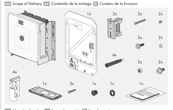
- Scope of Delivery: Verify all components are present before starting.
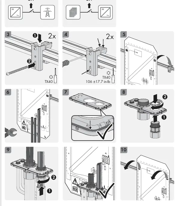
- Mounting: Follow the graphical instructions for mounting the inverter. Ensure the unit is mounted securely.
Electrical Connections
All electrical connections must be made according to local standards and the specifications in this manual.
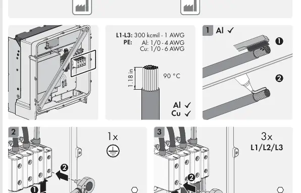
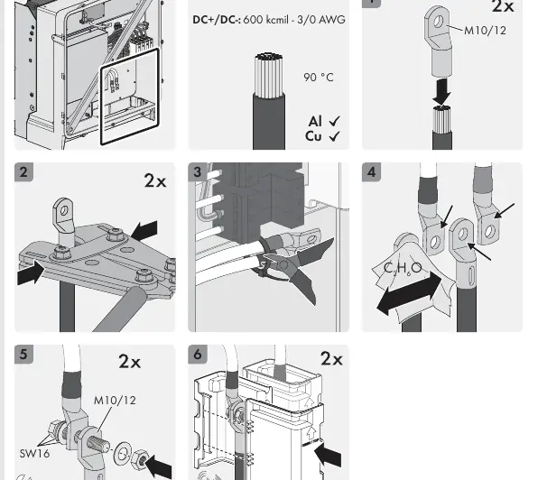
- AC Connection: Ensure the AC circuit breaker is disconnected and secured. Follow the torque specifications for live bolted connections.
- DC Connection: Install an external DC load-break switch between the inverter and the PV array. Ensure PV modules are compatible and of protection class II.
- Network Connection: Connect the network cable to the Ethernet interface. Ensure suitable surge protection is used for outdoor cable runs.
Commissioning and Configuration
Once installation is complete, proceed with commissioning:
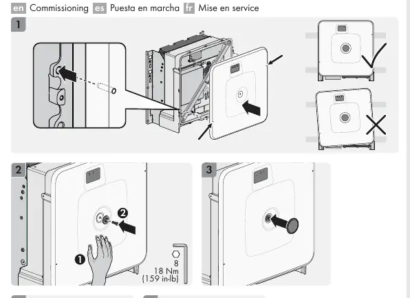
- Ensure all connections are secure and the enclosure is closed.
- Switch on the AC circuit breaker.
- Access the user interface via the network connection (IP address or URL provided in the manual).
- Configure the country data set correctly to avoid grid operator issues.
- Set the installer password and complete the system registration.
Technical Data
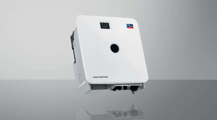
The inverter is designed for commercial and industrial use. It converts DC from PV arrays into grid-compliant three-phase AC. Key parameters include a maximum DC input voltage of 1500 V and compatibility with medium-voltage transformers.
Official resources from the manual
Practical help
Common problems
Ground fault detected
Disconnect the product from all voltage sources, ensure it cannot be reconnected, and wait 5 minutes before touching any parts.
Overvoltage risk
Ensure all devices in the same network are integrated into the existing overvoltage protection system.
Communication failure
Check the network cable connection and ensure the Ethernet interface is properly configured.
Before use
- Verify that the installation environment is free of sand and dust.
- Ensure ambient temperature is not below -5°C (23°F) before opening the enclosure.
- Confirm that the country data set is set correctly for your region.
- Ensure all personnel are qualified to perform the required tasks.
- Check that all necessary tools are available, including torque wrenches.
Specs in practice
- Protection class
- I - In accordance with IEC 61140.
Images and diagrams
- Mounting: Shows the 4-point mounting process and weight handling requirements.
- AC Connection: Details cable sizing (Al/Cu) and torque specifications for L1-L3 and PE connections.
- DC Connection: Details cable sizing and grounding requirements for DC+/DC- inputs.
Model compatibility
- Compatible with PV modules of protection class II (IEC 61730, application class A).
- Must be operated with a suitable medium-voltage transformer.
- The low-voltage side of the transformer must be configured in a star formation with a grounded neutral point.

Manual page author
Emily Carter
User documentation editor
Prepares concise manual descriptions and highlights the most useful setup, operation, and maintenance information for readers.