Power / Energy Storage Systems
Quick Installation Guide for Solplanet ASW 125K Liquid Cooled Energy Storage Cabinet
A comprehensive quick installation guide for the Solplanet ASW 125K Liquid Cooled Energy Storage Cabinet. Includes safety instructions, mounting requirements, electrical wiring procedures, communication setup, and parallel operation...
Table of contents
Manual images
Click an image to enlargeQuick Installation Guide Overview
This guide provides essential information for the installation, commissioning, and configuration of the Solplanet ASW 125K Liquid Cooled Energy Storage Cabinet. It is intended for use by trained professionals. Always refer to the full user manual for detailed procedures and updates.
Safety Instructions
Installation and maintenance must be performed by qualified professionals only. Failure to follow these instructions may result in serious injury or death.
- High Voltage Hazard: Battery strings produce high-voltage DC power. Do not touch terminals or cables.
- PPE Requirements: Always wear insulating clothing, rubber boots, goggles, safety helmets, and rubber gloves.
- Temperature Limits: The operating temperature range is -25°C to 55°C. The optimal range is 18°C to 28°C. Exceeding these limits may trigger alarms or reduce battery cycle life.
- Maintenance: Never perform maintenance while the system is powered on. Always verify zero voltage before touching terminals.
Product Overview
The cabinet includes various internal components such as the energy storage converter (PCS), lightning arresters, liquid cooling unit, and control modules. Refer to the schematic diagram for the location of the display screen, fault indicators, and emergency stop (Scram) button.
Mounting and Installation
Ensure the foundation meets the load-bearing requirements and provides adequate space for maintenance. The installation environment must allow for proper cable routing and cooling.
- Unpacking: Use a forklift (rated load 5T) for handling. Follow the step-by-step disassembly of the steel belt box, ensuring the cabinet is not dragged.
- Handling: Use flexible straps for crane lifting, ensuring the hook is at the center of gravity and the swing angle is less than 10°.
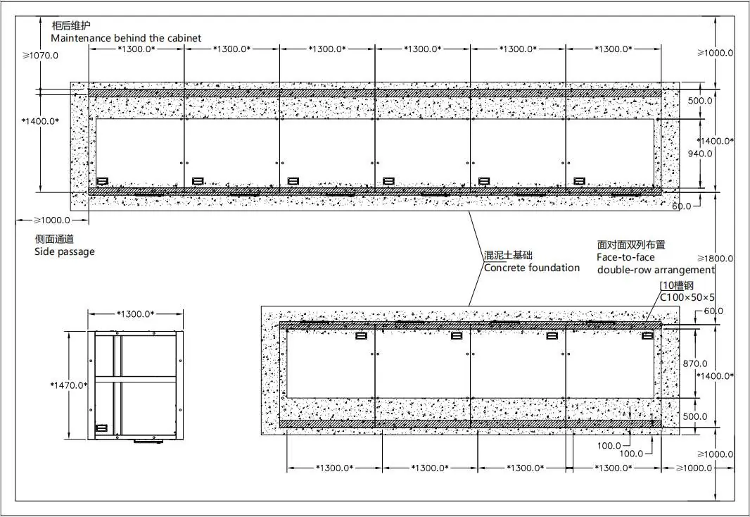
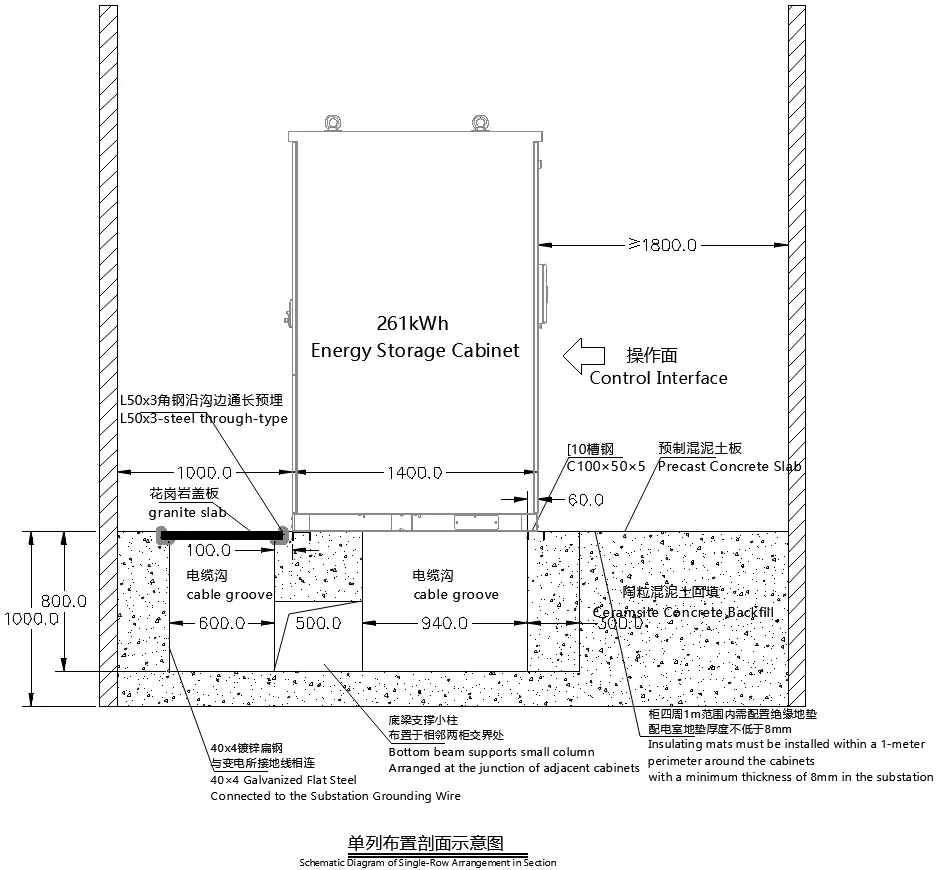
- Foundation: Follow the specific ground foundation requirements, including cable groove dimensions and concrete slab specifications.
Electrical Installation
Proper electrical connection is critical for system safety and performance.
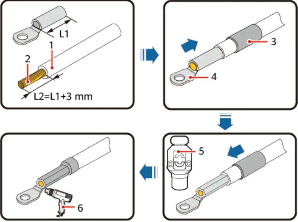
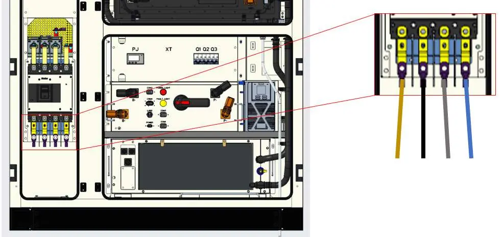
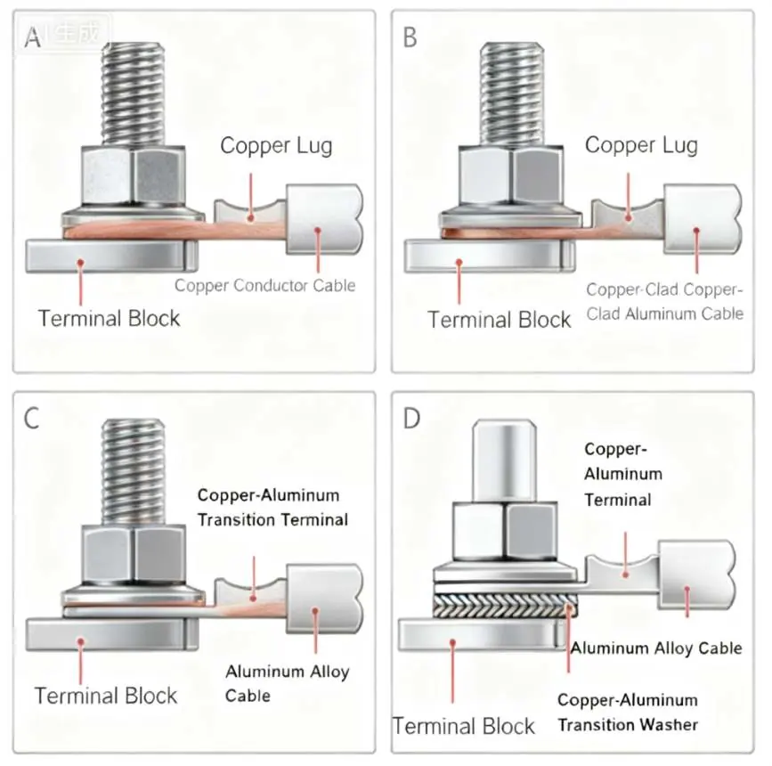
- Power Cables: Use cables within the 95mm² to 120mm² range. Use M10 copper terminals. Ensure crimping is performed at least twice.
- Torque: Tighten connections to a recommended torque of 16-18 N·m.
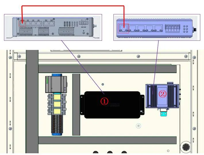
- Communication: Use outdoor dedicated CAT6 shielded network cables (23AWG-24AWG). Follow the 568B wiring standard for RJ45 connectors.
- Grounding: The cabinet must be reliably grounded. The connection resistance between the cabinet and the field grounding point must be less than 0.1Ω.
Parallel Operation
When connecting multiple cabinets in parallel, follow these guidelines:
- Debugging: Perform single-machine debugging before expanding to multi-machine operation.
- Expansion: Increase the number of parallel machines gradually, retesting load distribution and protection at each step.
- Communication: For systems with more than 5 cabinets, a secondary EMS, switch, and router are required to link the systems.
Fire Sealing
Fire-resistant mud is used to seal cable penetrations and cabinet gaps to prevent the spread of flames and smoke.
- Preparation: Clean the area of dust, oil, and rust.
- Application: Knead the fireproof mud until soft and plastic. Fill gaps slowly to ensure no cavities or bubbles remain.
- Inspection: Ensure a seamless package with no gaps. Use a craft knife to remove excess material.
Contact Information
For technical support, contact the Solplanet Service Department. Have your product serial number, fault code, installation location, and warranty card ready.
EMEA: [email protected]: [email protected]: [email protected] Greater China: [email protected]: [email protected]
Manufacturer information
Solplanet
Practical help
Common problems
System alarm or protection triggered
Verify the operating temperature is within -25°C to 55°C. Check for any abnormal load conditions.
Communication failure in parallel system
Ensure CAT6 shielded cables are used. If more than 5 cabinets are connected, verify the installation of the secondary EMS, switch, and router.
Cable connection overheating or failure
Verify the connection torque is 16-18 N·m and that the correct terminal size (M10) and cable gauge (95-120mm²) were used.
Before use
- Confirm all output switches are in the open state.
- Verify the installation environment temperature is within the specified range.
- Ensure all personnel are wearing appropriate PPE.
- Check that the foundation is level and meets load-bearing requirements.
- Verify that the cabinet is reliably grounded (resistance < 0.1Ω).
Specs in practice
- Operating Temperature
- -25°C to 55°C (Optimal: 18°C to 28°C).
- Recommended Torque
- 16-18 N·m for power cable connections.
- Cable Specification
- 95mm² to 120mm² power cables with M10 terminals.
- Communication Cable
- Outdoor dedicated CAT6 shielded network cable (23AWG-24AWG).
Images and diagrams
- Internal components diagram identifies 31 parts including the converter, cooling unit, and control modules.
- Foundation diagram details the required concrete slab and cable groove layout.
- Wiring diagrams illustrate the correct power line input and communication cable connections for single and parallel configurations.
Model compatibility
- Requires professional installation by trained personnel.
- Parallel operation for >5 cabinets requires additional hardware (secondary EMS, switch, router).

Manual page author
Emily Carter
User documentation editor
Prepares concise manual descriptions and highlights the most useful setup, operation, and maintenance information for readers.