Power / Solar Inverters
User Manual for Solplanet ASW 05-12kH-T2 Three Phase Hybrid Inverter
Comprehensive user manual for the Solplanet ASW 05-12kH-T2 series three-phase hybrid inverters. This guide covers installation, electrical connection, commissioning, app setup, and troubleshooting.
Table of contents
Manual images
Click an image to enlargeQuick guide from the manual
This manual provides essential instructions for the installation, commissioning, and operation of the Solplanet ASW 05-12kH-T2 series three-phase hybrid inverters. Before starting, ensure you are a qualified person with knowledge of inverters, batteries, and electrical safety. Always disconnect all voltage sources before performing any work on the device.
Inverter overview
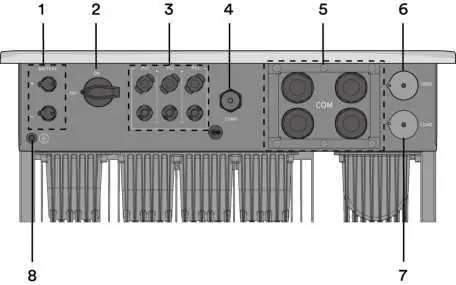
The inverter features a display area with LED indicators for status monitoring (Solar, Battery, Error, EPS, Grid). It includes multiple interfaces for communication, including Ai-Dongle, RS485, and CAN, supporting parallel operation and third-party monitoring devices.
Mounting
Ensure the mounting surface is solid (concrete or masonry) and can support four times the weight of the inverter. Maintain recommended clearances (at least 500mm) for ventilation. Do not install the inverter horizontally or with a tilt. Use the provided wall bracket and follow the step-by-step mounting procedure to secure the unit.
Electrical connection
Electrical connections must be performed by qualified personnel. Ensure all circuit breakers are switched off and secured before starting. The inverter supports various grid types (TN-S, TN-C, TN-C-S, TT). Follow specific procedures for connecting the Grid, EPS Load, DC (PV modules), Battery, and communication equipment. Ensure correct polarity for all DC connections.
Commissioning and operating
Before commissioning, inspect all connections. Use the Solplanet App to configure the inverter, set the grid code, operation mode, and battery parameters. Once configured, turn on the breakers to start the system. Observe the LED indicators to confirm normal operation.
Troubleshooting
If an error occurs, check the event message on the LCD or app. Common issues include grid frequency/voltage faults, isolation faults, and communication errors. Always disconnect the inverter from all sources and wait for LEDs to go out before troubleshooting.
Maintenance
Clean the DC switch contacts annually by rotating the handle from ON to OFF five times. Keep air inlets and outlets clear of obstructions to ensure proper cooling. Shut down the machine and wait 30 minutes before cleaning the air inlet/outlet.
Manufacturer information
Solplanet
Practical help
Common problems
Grid frequency fault (Error 33)
Check grid and EPS frequency. If fluctuations are frequent, contact the grid operator or modify operating parameters.
Grid voltage fault (Error 34)
Check grid voltage at the connection point. If outside permissible range, contact the electric utility company.
Isolation fault (Error 38)
Check PV array insulation to ground (must be > 1 Mohm) and inspect all PV cables and modules.
Over temperature fault (Error 40)
Check if airflow to the heat sink is obstructed and ensure ambient temperature is not too high.
Meter or CT loss (Error W192)
If CT is enabled, check phase sequence and connector. If meter is enabled, check communication connection.
Before use
- Ensure the inverter DC switch and external circuit breaker are disconnected.
- Verify the inverter is correctly mounted with the wall bracket.
- Check that the communication cable and AC connector are correctly wired and tightened.
- Confirm the DC voltage of the strings does not exceed the inverter's limits.
- Verify the DC voltage has the correct polarity.
- Ensure the grid voltage at the connection point complies with the inverter's specifications.
Specs in practice
- Maximum input voltage
- 1100 V; do not exceed this voltage to avoid destroying the inverter.
- Degree of protection
- IP66; suitable for indoor and outdoor applications.
- Cooling method
- Natural convection; ensure air inlets and outlets are not blocked.
- Max. operating altitude
- 4000 m; derating applies above 3000 m.
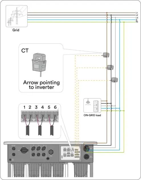
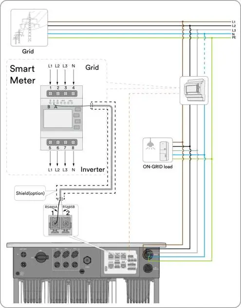
Images and diagrams
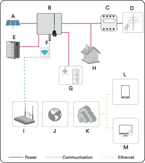
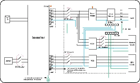
- The system diagram shows the connection of PV strings, battery, inverter, smart meter, and grid.
- For Australia/New Zealand, the neutral cable of the On-grid side and EPS side must be connected together per AS/NZS 3000.
- Parallel system wiring requires consistent phase sequence for all inverters.
Model compatibility
- Only use intrinsically safe lithium-ion batteries approved by AISWEI.
- Only Eastron and CHINT meters are supported.
- CT should not be used in a parallel system.

Manual page author
David Miller
Documentation analyst
Organizes user manual content into clear summaries, with attention to model details, product context, and everyday usability.