Power / Solar Inverters
Installation Guide for Solplanet ASW 3000/3680/4000/5000-S Solar Inverter
Quick installation and setup guide for Solplanet ASW 3000/3680/4000/5000-S series solar inverters. Includes mounting instructions, AC/DC wiring, communication setup, and technical specifications.
Table of contents
Manual images
Click an image to enlargeQuick guide from the manual
This document provides essential installation and commissioning steps for the Solplanet ASW 3000/3680/4000/5000-S series solar inverters. Only qualified technicians should perform installation. Ensure all DC switches and AC circuit breakers are disconnected before starting any electrical work. The inverter must be grounded firmly to prevent electrical shock.
Mounting
The inverter should be installed out of reach of children in an environment with an ambient temperature below 40°C. Avoid direct sunlight, rain, or snow; a protective roof is recommended. The unit is suitable for solid vertical walls or tilted backwards by a maximum of 15°. Do not install on plasterboard or similar materials.
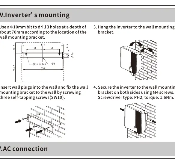
- Drill 3 holes with a 10mm bit to a depth of 70mm using the wall mounting bracket as a template.
- Insert wall plugs and fix the bracket using self-tapping screws (SW10).
- Hang the inverter onto the bracket.
- Secure the inverter on both sides using M4 screws (torque: 1.6Nm).
AC connection
All electrical installations must comply with local and national rules. The AC cable must be prepared with a ferrule according to DIN 46228-4.
- Loosen the swivel nut of the AC connector.
- Insert the crimped conductors into the corresponding terminals.
- Tighten the screws using the provided Allen key (torque: 2.0Nm).
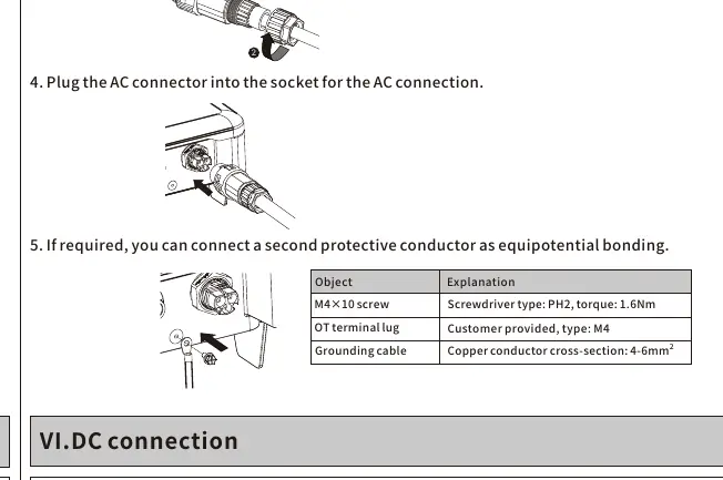
- Plug the AC connector into the socket on the inverter.
- Ensure the PE conductor is 2mm longer than the L and N conductors.
DC connection
Before connecting, ensure PV modules have good insulation against the ground. The open-circuit voltage of the PV modules must not exceed the maximum input voltage of the inverter on the coldest day.
- Check the polarity of DC cables.
- Ensure the DC switch is disconnected.
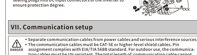
- Insert the DC plug connectors with sealing plugs into the inverter's DC input connectors to ensure the required protection degree.
- Do not disconnect DC connectors under load.
Communication setup
Communication cables must be CAT-5E or higher-level shielded cables. Keep them separate from power cables to avoid interference.
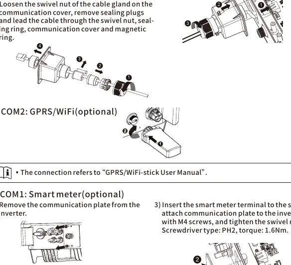
- RS485: Loosen the swivel nut on the communication cover, remove sealing plugs, and route the cable through the magnetic ring and cover. Connect to the socket and tighten the swivel nut (torque: 1.6Nm).
- Smart Meter: Remove the communication plate, route the cable through the gland, press the latch of the smart meter terminal to insert the cable, and reattach the plate.
Commissioning
Before starting, verify that the inverter is grounded, ventilation is adequate, and grid voltage is within the permitted range. Ensure all sealing plugs are tight.
- Switch on the AC circuit breaker between the inverter and the grid.
- Switch on the DC switch.
- The inverter will start automatically when sufficient DC power is applied and grid conditions are met.
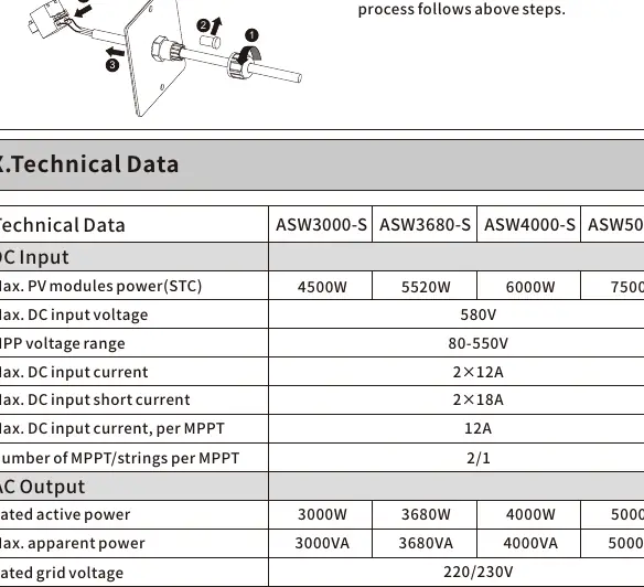
Technical data
The series supports a maximum DC input voltage of 580V and an MPP voltage range of 80-550V. The operating temperature range is -25°C to +60°C. The unit features IP65 protection and convection cooling.
Manufacturer information
Solplanet
Practical help
Common problems
PE grounding error
Ensure the inverter is grounded firmly. Check the ground connection and contact AISWEI service if the error persists.
Inverter noise
This may occur if installed on walls made of plasterboard or similar materials; ensure installation on a solid wall.
Communication interference
Ensure communication cables are separated from power cables and use CAT-5E or higher-level shielded cables.
Before use
- Ensure the installation site is out of reach of children.
- Verify the mounting wall is solid and vertical (or tilted max 15°).
- Check that the ambient temperature is <= 40°C.
- Ensure all DC switches and AC circuit breakers are disconnected.
- Verify PV module insulation against ground.
- Check that the open-circuit voltage of PV modules does not exceed 580V.
Specs in practice
- Max. DC input voltage
- 580V; must not be exceeded on the coldest day.
- Degree of protection
- IP65; suitable for outdoor use with protection.
- Max. operating altitude
- 4000m; derating applies above 3000m.
- AC connection torque
- 2.0Nm; use the provided Allen key.
Images and diagrams
- Mounting bracket requires 3 holes drilled 70mm deep.
- AC cable stripping: 13mm for conductors, 53mm for outer sheath.
- PE conductor must be 2mm longer than L and N conductors.
Model compatibility
- PV modules must be protection class II (IEC 61730, application class A).
- PV modules with high capacitance to ground must not exceed 1μF.
- Communication cables must be UV-resistant for outdoor use.

Manual page author
Emily Carter
User documentation editor
Prepares concise manual descriptions and highlights the most useful setup, operation, and maintenance information for readers.