Electronics / Security Cameras
Quick Start Guide for Speco Technologies 04BDD1M Network Camera
Quick start guide for the Speco Technologies 04BDD1M network camera. Includes installation steps, wiring diagrams, web interface login, and safety precautions.
Table of contents
Manual images
Click an image to enlargeQuick guide from the manual
This document provides essential steps for installing and configuring the Speco Technologies 04BDD1M network camera. Key requirements include a 12VDC Class 2 power supply or a PoE switch/injector. The camera is set to DHCP by default, and the web interface can be accessed using the IP Scanner tool with default credentials: admin / 1234.
Important Safeguards
- Electrical Safety: Use only a certified 12VDC Class 2 power supply. Do not connect two power sources simultaneously. Ensure the device is grounded.
- Environment: Install in a cool, dry place away from direct sunlight, heat sources, and extreme temperatures. Avoid electromagnetic radiation.
- Maintenance: Shut down and unplug before maintenance. Clean the lens with a blower or a dry soft cloth. Do not touch the CMOS sensor.
Package Contents
Ensure the following items are included in the package:
- Camera
- Quick start guide
- CD
- Drill Template
- 4 tapping screws and 1 machine screw
- 4 Plastic plugs
- Rubber plug
- Junction box
Device Overview
The camera features several connectors and components:
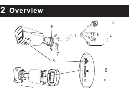
- 1: Ethernet connector
- 2: Audio input connector
- 3: Alarm input/output
- 4: Power connector
- 5: Speaker
- 6: Fixed ring
- 7: Mounting base
- 8: Micro SD card slot
- 9: Reset button
Installation
- Preparation: Ensure the mounting surface can support three times the weight of the camera.
- Junction Box: Open the mounting base and upper cover. Install the junction box onto the wall using the provided screws.
- Mounting: Mount the rubber plug into the gap of the mounting base and fasten the camera onto the base.
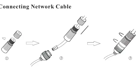
- Cable Connection: Connect the necessary cables. For outdoor installations, it is recommended to use the water-proof connector.
- Adjustment: Loosen the fixed ring to adjust the camera angle (360° pan, 90° tilt), then tighten the ring to secure the position.
Web Operation and Login
To access the camera via a web browser:
- Ensure the camera and PC are on the same local network.
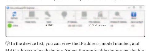
- Install the IP Scanner from the provided CD or download it from https://www.specotech.com/ip-scanner/.
- Run the scanner to find the camera's IP address.
- Double-click the device in the list to open the web viewer or enter the IP address directly into your browser.
- Log in using the default username admin and password 1234.
Official resources from the manual
Practical help
Common problems
Camera not powering on
Ensure you are using a certified 12VDC Class 2 power supply or that the PoE switch/injector is correctly connected.
Poor IR functionality or reflection
Ensure the dome cover is clean. Use professional optical cleaning methods; improper cleaning can damage the surface.
Cannot find camera on the network
Verify that the camera and PC are connected to the same local network. Use the IP Scanner tool to locate the device.
Before use
- Verify the wall or ceiling is strong enough to support three times the camera's weight.
- Check that all package components (screws, plugs, junction box) are present.
- Ensure a 12VDC power supply or PoE source is available.
- Have a network cable ready for connection.
- Ensure you have a PC on the same network for initial configuration.
Specs in practice
- 12VDC Class 2
- Required power input if not using Power over Ethernet (PoE).
Images and diagrams
- The overview diagram identifies all external connectors, including Ethernet, Audio, Alarm, and Power.
- The installation diagrams illustrate the step-by-step process of mounting the junction box and attaching the camera.
- The cable connection diagram shows how to assemble the water-proof connector for outdoor use.
Model compatibility
- Designed for both indoor and outdoor use (water-proof connector recommended for outdoor).
- Requires 12VDC Class 2 power supply or PoE switch/injector.

Manual page author
Emily Carter
User documentation editor
Prepares concise manual descriptions and highlights the most useful setup, operation, and maintenance information for readers.