Electronics / Security Cameras
Quick Start Guide for Speco Technologies 04D9 Network Camera
A quick start guide for the Speco Technologies 04D9 network camera. Includes installation instructions, wiring diagrams, web interface login details, and maintenance tips.
Table of contents
Manual images
Click an image to enlargeQuick Guide from the Manual
This document provides essential instructions for installing and configuring the Speco Technologies 04D9 network camera. Key requirements include using a 12VDC Class 2 power supply or PoE, ensuring the mounting surface can support three times the camera's weight, and using the provided IP Scanner software for initial network configuration. The default login credentials are admin for the username and 1234 for the password.
Safety and Maintenance
Electrical Safety: Use only a certified 12VDC Class 2 power supply. Do not connect two power sources simultaneously to avoid device damage. Ensure the product is grounded.
Environment: Do not install near heat sources, power lines, or radar equipment. Ensure the installation environment is within the specified temperature and humidity range. Use weatherproofing hardware for outdoor installations.
Maintenance: Shut down and unplug the device before maintenance. Do not touch the CMOS sensor. Clean the lens with a blower or an oil-free soft brush. For grease or fingerprints, use an oil-free cotton cloth or paper soaked with alcohol or detergent, wiping from the center outward.
Package Contents
Ensure the following items are included in the package:
- Camera
- Quick start guide
- CD
- 8 Plastic screw anchors
- 8 Screws (PA 4x25mm)
- Rubber plug
- 4 Rubber o-rings for screws
- Screwdriver
- 4 Screws (PM 4x16mm)
- Junction box
- Drill template
Device Overview
The camera features the following connectors and components:
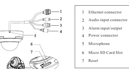
- 1: Ethernet connector
- 2: Audio input connector
- 3: Alarm input/output
- 4: Power connector
- 5: Microphone
- 6: Micro SD Card Slot
- 7: Reset button
Installation
Preparation: Ensure the wall or ceiling is strong enough to withstand three times the weight of the camera.
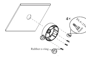
- Attach the drill template to the desired location and drill the necessary holes.
- Install the junction box onto the wall using the provided screws.
- Remove the trim ring from the gap of the camera.
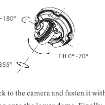
- Loosen the screws to open the lower dome.
- Connect the cables, mount the rubber plug to the gap of the mounting base, and fasten the camera onto the junction box.
- Perform three-axis adjustment by viewing the image on a monitor to achieve the optimum angle.
- Install the lower dome back to the camera, fasten with screws, put the trim ring back, and remove the protection film.
Web Operation and Login
The camera is set to DHCP by default. To access the web interface:
- Ensure the camera and PC are on the same local network.
- Install the IP Scanner from the provided CD or download it from https://www.specotech.com/ip-scanner/.
- Run the scanner to find the device, then double-click the device in the list to open the web viewer.
- Log in using the default username admin and password 1234.
Official resources from the manual
Practical help
Common problems
Device not powering on
Ensure a certified 12VDC Class 2 power supply is connected or use a PoE switch/injector. Do not connect two power sources at the same time.
Dirt or grease on the lens
Use a blower or oil-free soft brush for dust. For grease/fingerprints, use an oil-free cotton cloth or paper soaked with alcohol or detergent, wiping from the center outward.
Before use
- Verify the wall or ceiling can support three times the camera's weight.
- Check that all package components are present.
- Ensure the camera and PC are connected to the same local network.
- Install the IP Scanner software from the CD or website.
- Remove the protection film after installation.
Images and diagrams
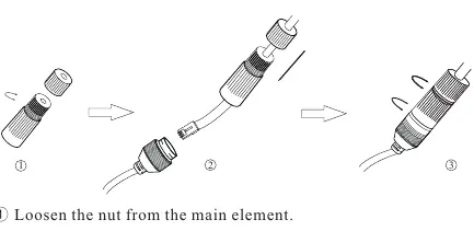
- The wiring diagram illustrates connections for Ethernet, Audio, Alarm, and Power, including the use of a water-proof connector for outdoor setups.
- The installation diagram shows the sequence of attaching the junction box, mounting the camera, and adjusting the dome.
Model compatibility
- Requires 12VDC Class 2 power supply or PoE switch/injector.
- Default login credentials: admin / 1234.
- Camera is set to DHCP by default.

Manual page author
Emily Carter
User documentation editor
Prepares concise manual descriptions and highlights the most useful setup, operation, and maintenance information for readers.