Electronics / Security Cameras
Quick Start Guide for Speco Technologies 04FD1 Network Camera
Quick start guide for the Speco Technologies 04FD1 network camera. Includes installation instructions, wiring diagrams, 3-axis adjustment, and web interface login details.
Table of contents
Manual images
Click an image to enlargeQuick Start Guide
This guide provides essential information for installing and configuring the Speco Technologies 04FD1 network camera. Please read all safety instructions before beginning installation.
Safety and Maintenance
- Electrical Safety: Use only a certified 12VDC Class 2 power supply. Do not connect two power sources simultaneously. Ensure the device is grounded.
- Environment: Install in a cool, dry place away from direct sunlight, heat sources, and extreme temperatures. Avoid exposure to water or electromagnetic radiation.
- Maintenance: Always shut down and unplug the device before maintenance. Do not touch the CMOS sensor. Use a blower for dust on the lens. For grease or fingerprints, use an oil-free cotton cloth with alcohol or detergent, wiping from the center outward.
Package Contents
Ensure all items are present before starting:
- Camera
- Quick start guide
- 4 tapping screws and 4 plastic plugs
- CD
- Drill template
- Rubber plug
- Junction box
- Screwdriver
Device Overview
The camera features the following connectors and components:
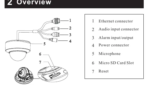
- Ethernet connector
- Audio input connector
- Alarm input/output
- Power connector
- Microphone
- Micro SD Card Slot
- Reset button
Installation
Before starting, ensure the mounting surface can support three times the weight of the camera.
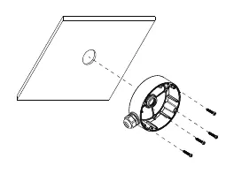
- Junction Box: Install the junction box onto the wall using the provided screws.
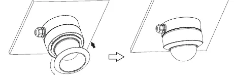
- Trim Ring: Rotate the trim ring anticlockwise to remove it from the camera.
- Lower Dome: Loosen the screws to open the lower dome.
- Mounting: Connect the cables, mount the rubber plug into the gap of the mounting base, and fasten the camera onto the junction box.
- Adjustment: Perform a 3-axis adjustment (Pan, Tilt, Rotation) while viewing the camera image on a monitor to achieve the optimum angle.
- Final Assembly: Reinstall the lower dome and fasten with screws. Place the trim ring back on and rotate clockwise until locked.
Connecting Network Cable
For outdoor installations, it is recommended to use the provided water-proof connector.
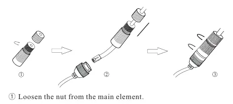
- Loosen the nut from the main element.
- Run the network cable (without RJ45 connector) through both elements.
- Crimp the cable with an RJ45 connector.
- Connect the cable to the water-proof connector, then tighten the nut and the main cover.
Note: DC 12V power supply is not required if a PoE switch or injector is used.
Web Operation and Login
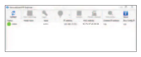
- Ensure the camera and PC are on the same local network. The camera is set to DHCP by default.
- Install the IP Scanner from the provided CD or download it from https://www.specotech.com/ip-scanner/
- Run the IP Scanner to find the device.
- Double-click the device in the list to open the web viewer, or enter the IP address in your browser.
- Default Login: Username is admin and password is 1234.
Official resources from the manual
Practical help
Common problems
Camera not powering on
Ensure you are using a certified 12VDC Class 2 power supply or a PoE switch/injector. Do not connect two power sources at once.
Dirt or grease on the lens
Use a blower for dust. For grease/fingerprints, use an oil-free cotton cloth with alcohol or detergent, wiping from the center outward.
Cannot find camera on network
Ensure the PC and camera are on the same local network. Use the IP Scanner tool to locate the device IP address.
Before use
- Verify the wall or ceiling can support 3x the camera weight.
- Check package contents against the provided list.
- Ensure a 12VDC Class 2 power supply is available (if not using PoE).
- Have a PC connected to the same local network for configuration.
- Ensure you have the IP Scanner software installed.
Specs in practice
- Pan/Tilt/Rotation
- Pan 0°~355°, Tilt 0°~67°, Rotation 0°~355°.
- Default Login
- Username: admin, Password: 1234.
- Power Requirements
- 12VDC Class 2 or PoE (Power over Ethernet).
Images and diagrams
- The wiring diagram illustrates connections for Ethernet, Audio, Alarm, and Power.
- The 3-axis adjustment diagram shows the range of motion for Pan, Tilt, and Rotation.
Model compatibility
- Outdoor installations require the use of the water-proof connector.
- Installation and repair must be performed by qualified personnel only.

Manual page author
Michael Turner
Technical manual editor
Reviews PDF manuals for structure, safety notes, and practical product details so readers can find the right information quickly.