Electronics / Security Cameras
Quick Start Guide for Speco Technologies 04VBIN Network Camera
Get started with your Speco Technologies 04VBIN network camera. This guide covers installation, wiring, web interface login, and maintenance instructions.
Table of contents
Manual images
Click an image to enlargeQuick Start Guide
This guide provides essential information for installing and operating the Speco Technologies 04VBIN network camera. Please read all safety instructions before beginning.
Important Safety Information
- Use only a certified 12VDC Class 2 power supply.
- Do not connect two power sources simultaneously to avoid device damage.
- Ensure the device is properly grounded to reduce the risk of electric shock.
- Install in a cool, dry place away from direct sunlight and heat sources.
- Do not touch the CMOS sensor; use a blower to clean dust from the lens.
- Professional optical cleaning methods are recommended for the enclosure to maintain IR functionality.
Package Contents
Ensure the following items are included:
- Camera
- Quick start guide
- CD
- Drill template
- 4 screws (PA 4x25mm)
- 1 screw (PWM3x5mm)
- 4 Plastic screw anchors
Device Overview
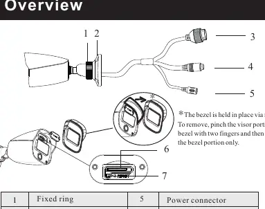
The camera features a fixed ring, mounting base, ethernet connector, audio input, power connector, micro SD card slot, and a reset button. The bezel is held in place by magnets; pinch the visor portion to remove it.
Installation
Before starting, ensure the wall or ceiling can support three times the weight of the camera.
- Attach the drill template to the desired location.
- Drill the screw holes and the cable hole.
- Route and connect the cables.
- Secure the mounting base with the camera to the wall using the provided screws.
Connecting Network Cable
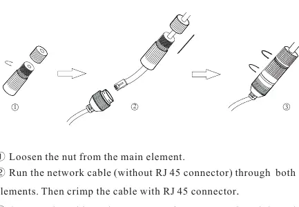
- Loosen the nut from the main element.
- Run the network cable (without RJ45 connector) through both elements.
- Crimp the cable with an RJ45 connector.
- Connect the cable to the waterproof connector and tighten the nut and main cover.
Adjustment
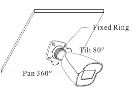
Preview the image on a monitor, then loosen the fixed ring to adjust the view angle (Pan 360°, Tilt 80°). Tighten the ring after adjustment.
Web Operation and Login
The camera is set to DHCP by default. Install the IP Scanner from the provided CD or download it from www.specotech.com/ip-scanner/.
Default Credentials:
- Username: admin
- Password: 1234
Official resources from the manual
Practical help
Common problems
Camera not powering on
Check if using a certified 12VDC Class 2 power supply or a PoE switch/injector.
Poor IR functionality
Ensure the enclosure is cleaned using professional optical methods; improper cleaning can cause IR reflection.
Cannot find camera on network
Ensure camera and PC are on the same local network; the camera is set to DHCP by default.
Before use
- Verify all package components are present.
- Ensure the mounting surface can support three times the camera's weight.
- Check that the power supply meets 12VDC Class 2 requirements.
- Install IP Scanner software from the provided CD or website.
Specs in practice
- 12VDC Class 2
- Required power supply specification to prevent damage.
- Pan 360° / Tilt 80°
- The range of motion for adjusting the camera view angle.
Images and diagrams
- The bezel is held by magnets; pinch the visor portion to remove.
- Waterproof connector assembly involves loosening the nut, threading the cable, crimping, and tightening.
Model compatibility
- Requires qualified personnel for installation and repair.
- Compatible with PoE switches or injectors (eliminates need for 12V power supply).

Manual page author
David Miller
Documentation analyst
Organizes user manual content into clear summaries, with attention to model details, product context, and everyday usability.