Electronics / Security Cameras
User Manual for Speco Technologies 04P25X PTZ Camera
Quick start guide for the Speco Technologies 04P25X PTZ camera. Includes installation steps, wiring diagrams, alarm connection instructions, and web interface login details.
Table of contents
Manual images
Click an image to enlargeQuick Guide from the Manual
This document provides essential setup and installation instructions for the Speco Technologies 04P25X PTZ camera. Before beginning, ensure you have all components from the package. The camera requires a 24VDC/AC power supply and should be installed by qualified personnel only. The default login credentials for the web interface are admin (username) and 1234 (password).
Safety and Maintenance
Electrical Safety: Use only a certified 24VDC/AC power supply. Do not connect two power sources simultaneously to avoid device damage. Ensure the product is properly grounded.
Environment: Install in a cool, dry place away from direct sunlight, heat sources, and extreme temperatures. Avoid exposure to water, violent vibration, or electromagnetic radiation, which may damage the CMOS sensor.
Maintenance: Always shut down and unplug the device before maintenance. Clean the lens with a blower to remove dust. Use a dry, soft cloth for the device body. Do not touch the CMOS sensor optic component.
Device Overview
The camera cable assembly includes the following ports:
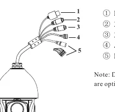
- LAN
- 3.5mm Audio Out
- 3.5mm MIC In
- Alarm In / Alarm Out
- Power
Installation
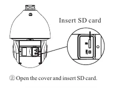
SD Card Installation: Loosen the two screws on the dome cover, open the cover, and insert the SD card.
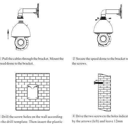
Speed Dome Mounting: Ensure the wall is strong enough to support the camera's weight. Power off the device during installation. Pull cables through the bracket, mount the dome to the bracket, and secure it with screws. Drill holes according to the template, insert plastic plugs, and fasten the bracket to the wall.
Cable Connection
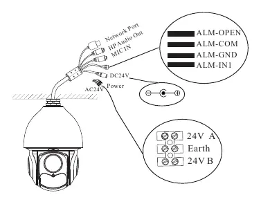
The camera supports various connections including network, audio, and alarm inputs/outputs. Ensure proper wiring for power (24V A/B) and grounding (Earth). Refer to the wiring diagram for specific pin assignments for alarm connections (ALM-OPEN, ALM-COM, ALM-GND, ALM-IN1).
Alarm Connection
Alarm Input: Features one independent alarm input port (ALM-IN1) and one grounding port (ALM-GND). For NO (Normally Open) type, connect 5V-12V DC voltage between ALM-IN1 and ALM-GND. For NC (Normally Closed) type, disconnect the voltage.
Alarm Output: Supports 1CH alarm output including OPEN and COM connections. It acts as a passive switch for external alarm devices.
Web Operation and Login
The camera is set to DHCP by default. Use the IP Scanner software provided on the CD to locate the device on your local network. Once identified, double-click the device in the list to open the web viewer, or enter the IP address directly into your web browser (Internet Explorer 8 or higher). Log in using the default credentials: admin / 1234.

Practical help
Common problems
Device not found on network
Ensure the camera and PC are connected to the same local network. The camera uses DHCP by default.
Cannot log in to web interface
Use the default username 'admin' and password '1234'.
Poor IR functionality
Use professional optical cleaning methods. Improper cleaning (e.g., using cloth) may cause IR reflection.
Before use
- Verify wall strength to support the dome camera's weight.
- Ensure the camera is powered off during installation.
- Check package contents for all components.
- Use a certified 24VDC/AC power supply.
- Ensure the camera is properly grounded.
Specs in practice
- Power Supply
- 24VDC or AC24V. Do not connect both sources simultaneously.
- Default Login
- Username: admin, Password: 1234.
Images and diagrams
- Cable assembly includes LAN, Audio Out, MIC In, Alarm I/O, and Power.
- Alarm wiring requires connecting ALM-IN1 and ALM-GND.
Model compatibility
- Web viewer requires Internet Explorer 8 or higher.

Manual page author
Emily Carter
User documentation editor
Prepares concise manual descriptions and highlights the most useful setup, operation, and maintenance information for readers.