Electronics / Security Cameras
Quick Start Guide for Speco Technologies O4B9 Network Camera
A quick start guide for the Speco Technologies O4B9 network camera. This manual covers safety precautions, package contents, hardware installation, network cable connection, and initial web interface login.
Table of contents
Manual images
Click an image to enlargeQuick guide from the manual
This document provides essential instructions for setting up the Speco Technologies O4B9 network camera. Key requirements include using a certified 12VDC Class 2 power supply or a PoE switch/injector. The camera is set to DHCP by default. Installation must be performed by qualified personnel, and the mounting surface must support three times the weight of the camera.
Safety and maintenance
- Electrical Safety: Use only a certified 12VDC Class 2 power supply. Do not connect two power sources simultaneously. Ensure the device is grounded.
- Environment: Do not install near heat sources, power lines, or radar equipment. Ensure the installation environment is within the specified temperature and humidity range.
- Maintenance: Shut down and unplug the device before maintenance. Do not touch the CMOS sensor. Use a blower to remove dust from the lens. Use a dry, soft cloth for cleaning the device.
Package contents
Ensure the following items are included in the package:
- Camera
- Quick start guide
- CD
- Junction box
- Screws (PA 4x25mm, PM 4x10mm, PWM3x5mm)
- Plastic screw anchors
- Drill template
- Rubber o-rings
Device overview
The camera features several external components:
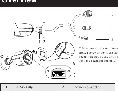
- Fixed ring: Used for adjusting the view angle.
- Mounting base: For securing the camera to the junction box.
- Connectors: Ethernet connector, audio input, and power connector.
- Micro SD card slot: Located on the camera body.
- Reset button: Located near the SD card slot.
Installation
- Ensure the wall or ceiling can withstand three times the weight of the camera.
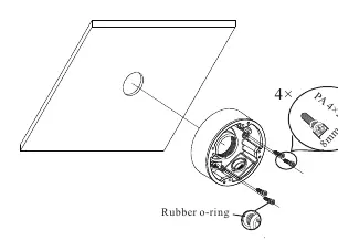
- Open the mounting base and upper cover of the junction box.
- Attach the drill template to the desired location and drill the necessary holes.
- Install the junction box onto the wall using the provided screws.
- Fasten the camera onto the mounting base.
- Connect the cables and install the camera onto the junction box.
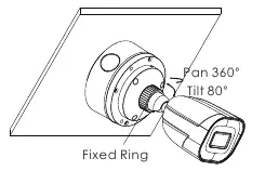
- Loosen the fixed ring to adjust the view angle (Pan 360°, Tilt 80°), then tighten it to secure the position.
Connecting network cable
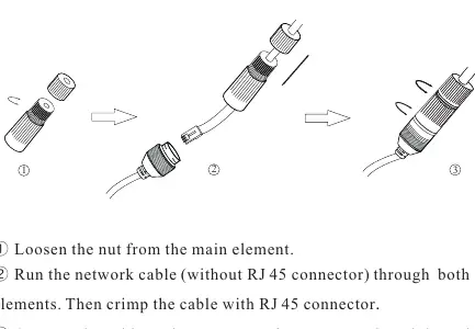
- Loosen the nut from the main element.
- Run the network cable (without RJ45 connector) through both elements.
- Crimp the cable with an RJ45 connector.
- Connect the cable to the water-proof connector, then tighten the nut and the main cover.
Note: It is recommended to install the security cap for outdoor installations.
Web operation and login
- Ensure the camera and PC are on the same local network.
- Install the IP Scanner from the provided CD or download it from www.specotech.com/ip-scanner/.
- Run the IP Scanner to find the camera's IP address.
- Double-click the device in the list to open the web viewer, or enter the IP address directly into a web browser.
- Default username is admin and the default password is 1234.
Official resources from the manual
Practical help
Common problems
Device not powering on
Ensure you are using a certified 12VDC Class 2 power supply or a PoE switch/injector. Do not connect both power sources at once.
Cannot find camera on network
Ensure the PC and camera are connected to the same local network. Use the IP Scanner tool to locate the device.
Dirt on lens
Use a blower to remove dust. For grease or fingerprints, use an oil-free cotton cloth or paper soaked with alcohol or detergent, wiping from the center outward.
Before use
- Verify all components from the package list are present.
- Ensure the mounting surface is strong enough to hold three times the camera's weight.
- Have a slotted screwdriver available for bezel removal.
- Ensure network cable is ready for crimping if using the waterproof connector.
Images and diagrams
- The overview diagram identifies the Ethernet, audio, and power connectors, as well as the reset button and SD card slot.
- The installation diagram shows the correct assembly of the junction box, rubber o-rings, and screws.
Model compatibility
- Outdoor installations require the use of the security cap.
- Installation and repair must be performed by qualified personnel only.

Manual page author
David Miller
Documentation analyst
Organizes user manual content into clear summaries, with attention to model details, product context, and everyday usability.