Electronics / Security Cameras
Speco Technologies O4D6N Network Camera Quick Start Guide
Quick start guide for the Speco Technologies O4D6N network camera. Includes installation instructions, wiring diagrams, mounting steps, and web interface login details.
Table of contents
Manual images
Click an image to enlargeQuick guide from the manual
The Speco Technologies O4D6N is a network camera designed for professional installation. Key requirements include a 12VDC Class 2 power supply or a PoE switch/injector. The camera features a 3-axis adjustment mechanism for precise positioning. Default login credentials for the web interface are admin and 1234.
Safety and Maintenance
- Electrical Safety: Use only a certified 12VDC Class 2 power supply. Do not connect two power sources simultaneously. Ensure the device is grounded.
- Environment: Install in a cool, dry place away from direct sunlight, heat sources, and extreme temperatures. Avoid exposure to water or electromagnetic radiation.
- Maintenance: Shut down and unplug before maintenance. Do not touch the CMOS sensor. Use a blower for dust on the lens. For grease or fingerprints, use an oil-free cotton cloth or paper soaked with alcohol or detergent, wiping from the center outward.
Package Contents
Ensure the following items are included in the package:
- Camera
- Quick start guide
- CD
- 8 Plastic plugs
- 8 Screws (PA 4x25mm)
- Rubber plug
- 4 Screw waterproof rings
- Screwdriver
- 4 Screws (PM 4x16mm)
- Junction box
- Drill template
Device Overview
The camera includes the following connectors and features:
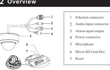
- 1: Ethernet connector
- 2: Audio input connector
- 3: Alarm input/output
- 4: Power connector
- 5: Microphone
- 6: Micro SD Card Slot
- 7: Reset button
Installation
Before starting, ensure the mounting surface can support three times the weight of the camera.
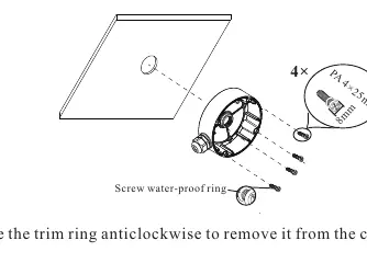
- Attach the drill template to the desired location and drill the necessary holes.
- Install the junction box onto the wall using the provided screws.
- Rotate the trim ring anticlockwise to remove it from the camera.
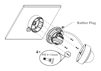
- Loosen the screws to open the lower dome.
- Connect the cables, mount the rubber plug into the gap of the mounting base, and fasten the camera onto the junction box.
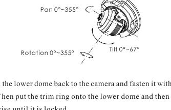
- Perform 3-axis adjustment (Pan, Tilt, Rotation) while viewing the camera image on a monitor to achieve the optimum angle.
- Reinstall the lower dome and fasten with screws. Put the trim ring back on and rotate clockwise until locked.
Web Operation and Login
The camera is set to DHCP by default.
- Ensure the camera and PC are on the same local network.
- Install the IP Scanner software from the included CD or download it from https://www.specotech.com/ip-scanner/.
- Run the IP Scanner to find the device.
- Double-click the device in the list to open the web viewer or enter the IP address directly into a web browser.
- Log in using the default username admin and password 1234. Follow prompts to install any required plugins.
Official resources from the manual
Practical help
Common problems
Camera not powering on
Verify the 12VDC power supply is connected correctly or ensure the PoE switch/injector is functioning.
Dirt or grease on the lens
Use a blower for dust. For grease, use an oil-free cloth with alcohol or detergent, wiping from the center outward.
Cannot find camera on network
Ensure the PC and camera are on the same local network. Use the IP Scanner software to locate the device.
Before use
- Verify the wall or ceiling can support three times the camera's weight.
- Ensure a 12VDC Class 2 power supply or PoE source is available.
- Check that all package components are present.
- Install the IP Scanner software on your PC.
Specs in practice
- 3-axis adjustment
- Allows manual adjustment of Pan (0-355°), Tilt (0-67°), and Rotation (0-355°) for optimal viewing angle.
Images and diagrams
- The wiring diagram illustrates connections for Ethernet, Audio, Alarm, and Power.
- The 3-axis adjustment diagram shows the range of motion for Pan, Tilt, and Rotation.
Model compatibility
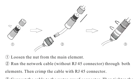
- Outdoor installations require the use of the included water-proof connector.
- Installation must be performed by qualified personnel only.

Manual page author
David Miller
Documentation analyst
Organizes user manual content into clear summaries, with attention to model details, product context, and everyday usability.