Home / Window Treatments
Style Selections 150-Ft Capacity Cabinet Hose Reel User Manual
Quick guide for the Style Selections 150-Ft Capacity Cabinet Hose Reel (SGY-GAR2). Includes assembly steps, installation instructions, operation tips, and maintenance advice.
Table of contents
Manual images
Click an image to enlargeQuick guide from the manual
This guide provides essential information for the assembly and operation of the Style Selections 150-Ft Capacity Cabinet Hose Reel. Before beginning, ensure you have a Phillips screwdriver and a clean surface for assembly. Always verify that your water supply pressure is below 100 PSI to prevent damage. If you encounter missing parts or issues, contact customer service at 877-888-8225.
Package Contents
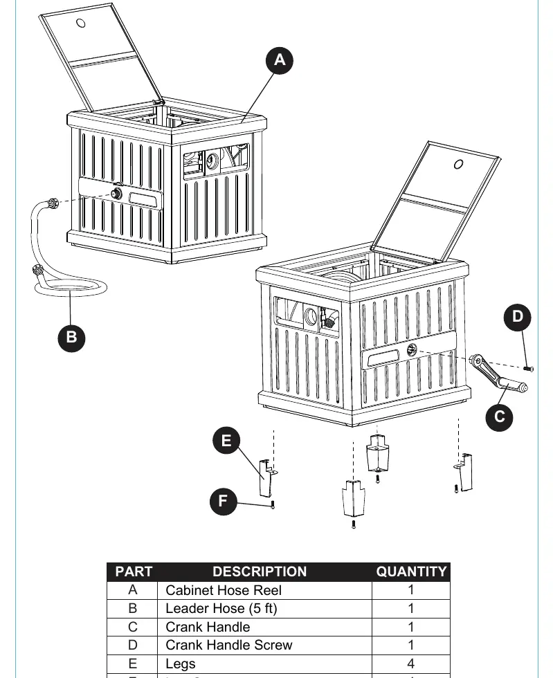
- A: Cabinet Hose Reel (1)
- B: Leader Hose (5 ft) (1)
- C: Crank Handle (1)
- D: Crank Handle Screw (1)
- E: Legs (4)
- F: Leg Screws (4)
Safety Information
- Connect only to water pressure below 100 PSI.
- Release pressure when the unit is not in use.
- Do not drink water from the hose.
- Wash hands after use.
- Ensure correct attachment of hoses to prevent cross-threading, which can cause permanent damage.
- Maximum capacity: 150-ft of 5/8-inch standard vinyl hose.
Assembly Instructions
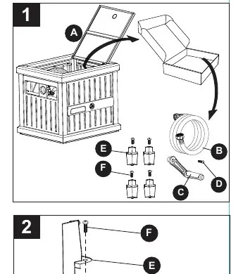
- Open the cabinet cover (A) and remove all parts (B, C, D, E, F) from the box.
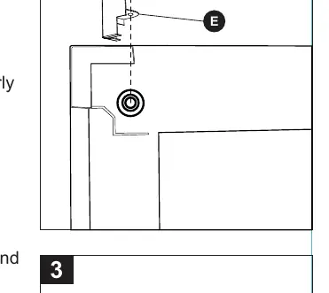
- Place the unit upside down on a clean surface. Install the 4 legs (E) using the leg screws (F). Ensure the open sides of the legs face inward and the holes are aligned before tightening.
- Turn the unit upright on a level surface. Attach the crank handle (C) to the side of the cabinet using the crank handle screw (D) with a Phillips screwdriver.
Installation
Attaching the Leader Hose:
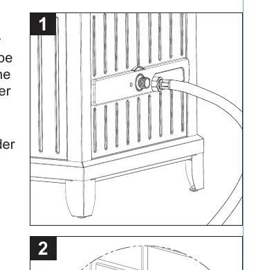
- Inspect both ends of the leader hose (B) to ensure rubber washers are properly seated.
- Connect one end to the in-tube on the exterior of the hose reel and the other to your water supply. Do not cross-thread.
Attaching the Water Hose:
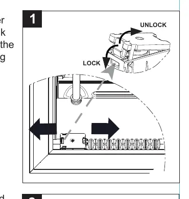
- Ensure the hose guide is aligned with the water system outlet. If necessary, lift the latch on the guide to adjust alignment.
- Verify rubber washers are inside the female fittings of your garden hose.
- Insert the hose through the guide and screw the female end onto the outlet tube. Tighten securely (pliers may be used if necessary).
- Attach your nozzle to the other end of the hose and check for leaks.
Operation
- Remove the required length of hose from the unit.
- Turn on the water at the faucet.
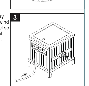
- To unwind: Pull the hose out in a straight line.
- To rewind: Walk the end back to the reel so the hose forms a "U" shape in front of the reel to assist in smooth winding.
Moving and Storing
Store the hose reel indoors during colder months. If the unit must remain in freezing conditions, disconnect the hose from the faucet and drain all water from both the hose and the reel to prevent damage to pipes and components.
Care and Maintenance
Always operate the product with care by following the operating instructions. Regularly check connections for leaks.
Warranty
This product is warranted by the manufacturer to the original purchaser for five (5) years from the date of purchase against defects in material and workmanship. The warranty is void if damage results from unauthorized repairs, improper maintenance, neglect, accident, or overloading beyond capacity.
Practical help
Common problems
Leaks at hose connections
Ensure rubber washers are properly seated in the female fittings. Use pliers to tighten the fitting if necessary.
Difficulty rewinding hose
Walk the end of the hose back to the reel so the hose forms a 'U' shape in front of the reel before cranking.
Missing parts
Do not attempt to assemble. Contact customer service at 877-888-8225 or [email protected].
Before use
- Verify all parts (A-F) are present.
- Ensure you have a Phillips screwdriver.
- Check that rubber washers are seated in all hose fittings.
- Confirm water supply pressure is below 100 PSI.
- Ensure the hose guide is aligned with the water outlet.
Specs in practice
- Hose Capacity
- Up to 150-ft of 5/8-inch standard vinyl hose.
- Max Water Pressure
- Must be below 100 PSI.
- Assembly Time
- Estimated 5-10 minutes.
Images and diagrams
- The assembly diagram shows the legs (E) being attached to the bottom corners with screws (F).
- The hose guide mechanism features a lock/unlock latch to align with the water outlet.
Model compatibility
- Designed for 5/8-inch standard vinyl hose.
- Hose is not included with the product.

Manual page author
David Miller
Documentation analyst
Organizes user manual content into clear summaries, with attention to model details, product context, and everyday usability.