Electronics / Audio Processors
User Manual for Taramps PRO 2.8S DSP Digital Audio Processor
Comprehensive user guide for the Taramps PRO 2.8S DSP Digital Audio Processor. Learn about installation, DSP settings, audio routing, crossover, limiter configurations, and technical specifications.
Quick answers from the manual
Quick answer
- The Taramps PRO 2.8S is a digital audio processor. It requires professional installation, supports 12V systems, and offers advanced audio control including routing, EQ, crossover, delay, and limiting. p. 1, 3
Key actions
- Reset to factory settings p. 12
- Adjust input gain p. 4
First start
- Upon first power-on, the processor will prompt for language selection. Rotate the encoder to choose and press to confirm. p. 4
Problems and fixes
Input clip LED lights up
Reduce the processor input gain.
p. 4
Forgotten password
Perform a factory reset by holding output keys 1 and 2 and the encoder center during power-up.
p. 12Maintenance and reset
- Factory reset: Hold output keys 1 and 2 + encoder center during power-up. p. 12
Technical specifications
| Parameter | Value | Meaning | Pages |
|---|---|---|---|
| Supply Voltage | 9 to 17V DC | Operating voltage range | p. 14 |
| Input Channels | 2 | Number of input channels | p. 14 |
| Output Channels | 8 | Number of output channels | p. 14 |
| Frequency Response | 10Hz to 22KHz | Audio frequency range | p. 14 |
Where to find it in the PDF
- DSP Overview p. 4
- Menu Structure p. 6
- Technical Features p. 14
Table of contents
Manual images
Click an image to enlargeQuick guide from the manual
The Taramps PRO 2.8S is a digital audio processor designed for professional audio systems. Important: Installation must be performed by a qualified professional. Always check the battery voltage (12V) before installing and ensure the unit is placed in a firm location away from heat, dust, and moisture. A 1A fuse must be installed on the positive wire close to the battery terminal.
DSP Overview
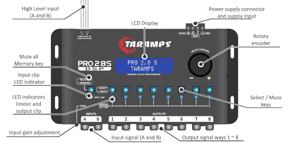
The front panel features an LCD display, a rotary encoder for navigation, and output selection keys. The input gain adjustment allows the DSP to accept signals up to 2V RMS (maximum sensitivity) or up to 9V RMS (minimum sensitivity). The input clip LED indicates if the signal is reaching the maximum limit; if it lights up, reduce the input gain.
Basic Operation
Upon first power-on, the processor will prompt for language selection. Rotate the encoder to choose the language and press the center to confirm. To access the main menu, press the center of the encoder. To return to the previous menu, perform a long press on the center of the encoder.
Audio Menu and Settings
The audio menu allows for detailed sound processing:
- I/O Routing: Configure internal connections between inputs (A, B, or A+B) and outputs.
- Graphic Equalizer: 15 bands with attenuation/gain up to 12dB (Standard mode only).
- Parametric Equalizer: Adjustable center frequency, gain, and Q factor.
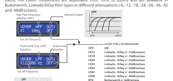
- Crossover: Set high-pass (HPF) and low-pass (LPF) filters with various slopes (Linkwitz-Riley and Butterworth).
- Delay: Adjust delay for system alignment based on transducer distance.
- Phase: Invert the phase of the channel output signal (0 or 180 degrees).
- Limiter: Protects speakers by limiting the maximum signal level. Available in Manual or Automatic modes.
Operating Modes
The PRO 2.8S operates in two modes:
- STANDARD MODE: Facilitates adjustment for common audio systems. Includes 15-band graphic EQ.
- DYNAMIC PEAK: Incorporates advanced limiter features for system protection.
Technical Features
The processor features 24-bit resolution and a 48kHz sampling rate. It supports 2 input channels and 8 output channels. The frequency response ranges from 10Hz to 22KHz. The unit operates on a supply voltage of 9 to 17V DC.
Maintenance and Reset
To reset the processor to factory settings (e.g., if the password is lost), turn on the processor while keeping the keys of outputs 1 and 2 and the center of the encoder pressed simultaneously. This will erase all user settings.
Practical help
Common problems
Input clip LED lights up
The signal is reaching the maximum limit. Reduce the processor input gain.
Forgotten password
Perform a factory reset by turning on the processor while holding output keys 1 and 2 and the center of the encoder simultaneously.
Distorted audio
Check input gain settings and ensure the limiter is properly configured for your system.
Before use
- Ensure installation is performed by a qualified professional.
- Use 1.5mm² (15 AWG) wire for power supply and 0.50mm² (20 AWG) for remote signal.
- Install a 1A fuse on the positive wire close to the battery terminal.
- Check battery voltage (12V) before installing.
- Ensure the unit is installed in a firm location away from heat sources and moisture.
Specs in practice
- Sampling rate
- 48 kHz.
- Input impedance
- 10K ohms (RCA) / 50 ohms (high level).
- Frequency response
- 10Hz to 22KHz.
Images and diagrams
- Input/Output Wiring: Shows connection from head unit (RCA or speaker wires) to processor inputs, and processor outputs to amplifiers.
- Crossover Filter: Illustrates HPF and LPF filter curves with various slopes (Linkwitz-Riley and Butterworth).
Model compatibility
- Compatible with 12V battery systems.
- Supports RCA low-level or high-level speaker inputs.

Manual page author
David Miller
Documentation analyst
Organizes user manual content into clear summaries, with attention to model details, product context, and everyday usability.