Electronics / Networking
Tenda 16/24-Port Gigabit Ethernet Switch Installation Guide
Quick installation guide for Tenda 16/24-Port Gigabit Ethernet Switch (TEG1016G/TEG1024G). Includes setup instructions for rack, wall, and desktop mounting, LED indicator explanations, and safety precautions.
Table of contents
Quick guide from the manual
This guide provides essential installation and setup instructions for the Tenda 16/24-Port Gigabit Ethernet Switch (models TEG1016G and TEG1024G). It covers physical mounting options, LED status interpretation, and basic troubleshooting steps to ensure proper operation.
LED indicators
The front panel features LED indicators to help monitor the device status:
- Power: Solid on indicates the device is powered on; Off indicates the device is powered off.
- Link/Act: Solid on indicates the device is connected but not active; Blinking indicates data is being transmitted; Off indicates no connection.
Installation
The switch supports three mounting methods:
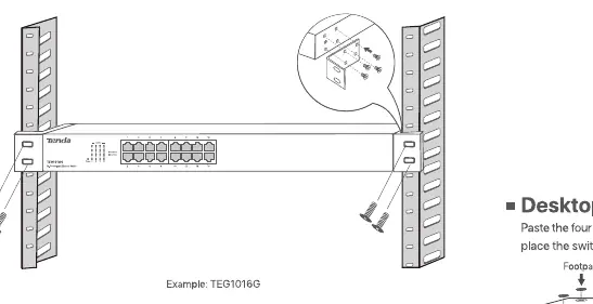
- Rack mounting: Designed for a standard 19-inch rack. Secure the switch to the rack using the provided L-shaped brackets and screws. Ensure the rack is stable, level, and properly grounded.
- Wall mounting: Use only on non-flammable walls. Attach the L-shaped brackets to both sides of the switch, then secure the switch to the wall using the provided expansion bolts.
- Desktop mounting: Attach the four provided footpads to the bottom of the switch. Place the switch on a large, clean, stable, and flat desktop.
Typical network topology
The switch connects to a router via an uplink port. Computers, printers, and IP cameras can be connected to the remaining LAN ports. The device supports MDI/MDIX, allowing the use of either straight-through or crossover cables.
Safety precautions
- The device is for indoor use only.
- For wall or rack mounting, the device is only suitable for mounting at heights ≤ 2m.
- Ensure the power cord is connected to the switch and the power jack properly.
- Do not block the ventilation openings.
- Keep away from heat sources such as radiators or heaters.
- Do not damage the ground conductor or operate the device in the absence of a well-installed ground conductor.
- Unplug the device when unused for long periods.
Troubleshooting
If you encounter issues, check the following:
- Power LED does not light up: Ensure the power cord is connected securely to the switch and the power outlet. Verify that the power outlet provides the required voltage.
- Link/Act LED is off: Ensure the Ethernet cable is connected properly between the switch and the device. Verify that the connected device is powered on and the cable length is within limits.
Practical help
Common problems
Power LED does not light up
Ensure the power cord is connected securely to the switch and the power outlet. Verify that the power outlet provides the required voltage.
Link/Act LED is off
Ensure the Ethernet cable is connected properly between the switch and the device. Verify that the connected device is powered on and the cable length is within limits.
Before use
- Ensure the rack is stable, level, and properly grounded.
- Verify the wall is non-flammable for wall mounting.
- Check that the power supply matches the device requirements.
- Ensure all Ethernet cables are within the supported length limits.
- Confirm the device is placed on a flat, stable surface if desktop mounting.
Images and diagrams
- The network topology diagram illustrates the switch connected to a router via an uplink port, with various devices like computers, printers, and IP cameras connected to the LAN ports.
Model compatibility
- Supports MDI/MDIX, allowing the use of either straight-through or crossover cables.

Manual page author
David Miller
Documentation analyst
Organizes user manual content into clear summaries, with attention to model details, product context, and everyday usability.