Music / Guitar Effects
Installation Manual for Thorn Bollard
Quick installation and wiring guide for Thorn Bollard (Wide, Slim MPL, Slim MGR). Includes mounting instructions, Master/Slave wiring configurations, MAS sensor settings, and technical specifications.
Table of contents
Manual images
Click an image to enlargeQuick Guide from the Manual
This document provides installation and wiring instructions for the Thorn Bollard series (Wide, Slim MPL, Slim MGR). Installation must be performed by a qualified person. The light source is not user-replaceable and must be handled by the manufacturer or a qualified service agent. Ensure proper drainage during installation to prevent water accumulation.
Mounting Instructions
The bollard must be installed securely using the specified torque settings. All screws should be tightened to 2.5 N.m. Ensure the base is mounted on a stable surface with adequate drainage to prevent water ingress, which can damage the unit.
Wiring and Master/Slave Configuration
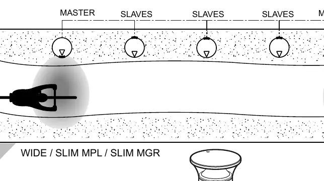
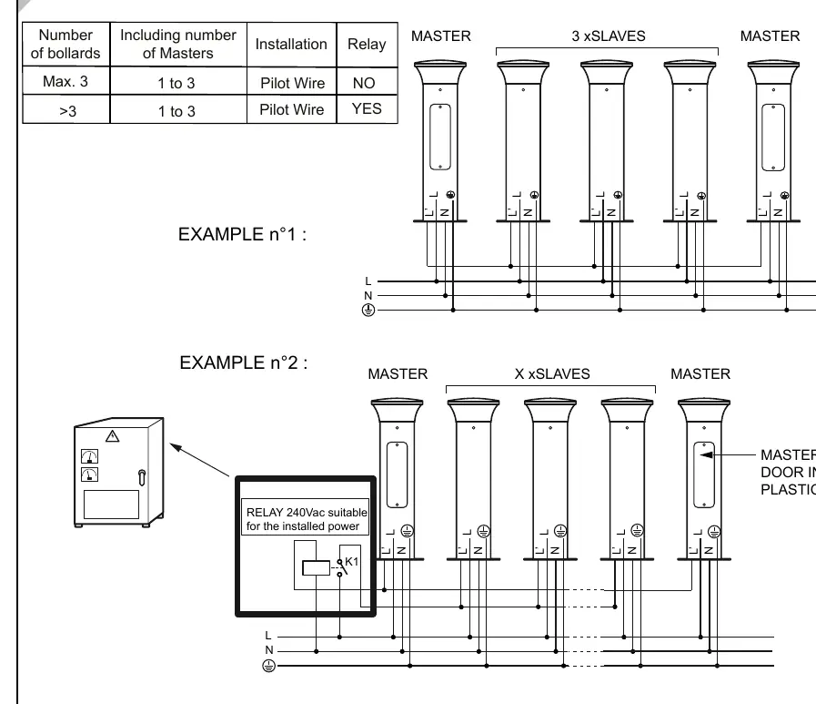
The system supports Master/Slave configurations for synchronized lighting control. Use the provided wiring diagrams to connect the units correctly. When connecting multiple bollards, ensure the pilot wire is connected according to the configuration (Master/Slave). For systems with more than 3 bollards, a relay is required.
MAS Sensor and Dimming Settings
For models equipped with MAS (Motion Detection):
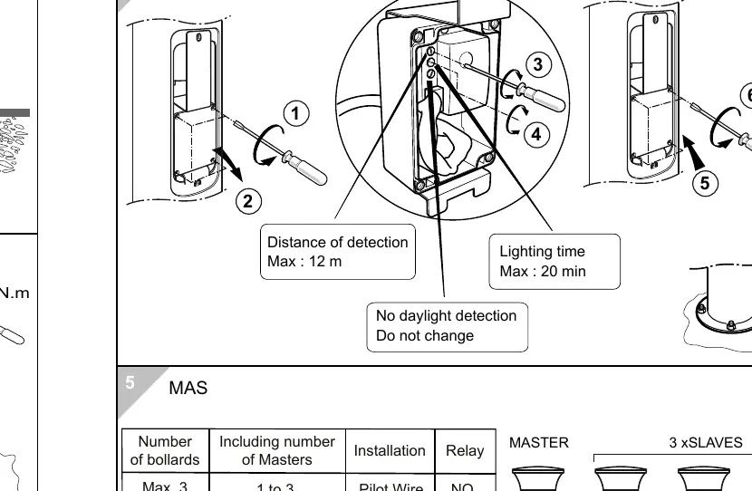
- Detection Distance: Max 12 meters.
- Lighting Time: Max 20 minutes.
- Daylight Detection: Do not change factory settings.
For RGB and Bi-Power/Dimming models, use the internal switches to adjust settings. Ensure the power is off before making adjustments to the internal switches.
Technical Specifications
- Protection Class: IP66 (Dust-tight and protected against heavy seas/water jets), IK10 (Impact protection).
- Electrical Class: Class I or Class II (refer to product label).
- Torque: 2.5 N.m for all mounting screws.
- Weight: Varies by model (Wide: 9.0kg, Slim MPL: 7.7kg, Slim MGR: 9.3kg).
Practical help
Common problems
Water ingress or accumulation at the base
Ensure proper drainage is installed at the base of the bollard during mounting.
Master/Slave units not synchronizing
Verify the pilot wire connection and ensure the relay is installed if the number of bollards exceeds 3.
Incorrect torque causing loose mounting
Tighten all mounting screws to exactly 2.5 N.m.
Before use
- Verify the product model (Wide, Slim MPL, or Slim MGR) and its electrical class (Class I or II).
- Ensure installation is performed by a qualified person.
- Prepare the mounting surface with adequate drainage.
- Check that all tools (e.g., T30 hollow bit) are available.
- Confirm the wiring configuration (Master/Slave) before starting electrical connections.
Images and diagrams
- The wiring diagrams illustrate how to connect Master and Slave units using a pilot wire.
- The MAS sensor diagram shows the detection range (12m) and timing settings (20m).
- The mounting diagrams detail the base dimensions and screw placement.
Model compatibility
- Light source is not user-replaceable.
- Systems with more than 3 bollards require an external relay.
- Ensure the relay used is 240Vac suitable for the installed power.

Manual page author
Emily Carter
User documentation editor
Prepares concise manual descriptions and highlights the most useful setup, operation, and maintenance information for readers.