Lighting / Outdoor Lighting
Installation Instructions for RAB WPLED 10W/13W LED Wall Pack
Installation guide for the RAB WPLED 10W/13W LED wall pack. Includes mounting instructions for junction boxes and recessed boxes, wiring diagrams for 0-10V dimming, photocell installation, and maintenance tips.
Table of contents
Manual images
Click an image to enlargeImportant Safety Information
Read all instructions carefully before installing the fixture. This product must be installed in accordance with the National Electrical Code and all applicable local codes by a person familiar with the construction and operation of the product. Ensure power is OFF before installing or maintaining the fixture. No user-serviceable parts are inside. For proper weatherproof function, ensure all gaskets are seated properly and all screws are tightened firmly. Apply weatherproof silicone sealant around the edge of the Back Box and/or Junction Box, especially on uneven wall surfaces. Seal all plugs and unused conduit entries.
Junction Box Mount for Conduit
This method is for applications where conduit wiring is necessary.
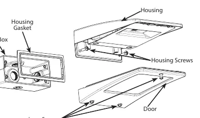
- Loosen and remove the (3) Lens Screws and remove the Door.
- Loosen and remove the (2) Housing Screws and remove the Housing from the Back Box. Keep the Housing Gasket intact.
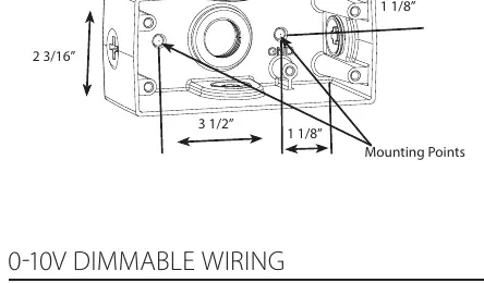
- Secure the Back Box to the mounting surface using hardware appropriate for that surface.
- Wire the fixture using UL-listed wire connectors according to NEC and local codes. Apply sealant to all unused conduit entry points.
- Place the Gasket between the Back Box and Housing. Re-mount the Housing to the Back Box, ensuring the Housing Gasket seals all around.
- Re-mount the Door to the Housing and tighten the (3) Lens Screws. Check the door gasket seal.
- The fixture can be mounted as an uplight.
Surface Mount for Recessed Box
This method is for use with recessed Junction Boxes and wiring.
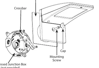
- Use the supplied Crossbar and mount it to the Recessed Junction Box with (2) screws.
- Place the Gasket on the back of the fixture to create a seal against the mounting surface.
- Wire the fixture to supply wires in the Recessed Box according to the wiring section.
- Use the 1/4 x 20 stainless steel Mounting Screw to attach the fixture to the Crossbar and tighten.
- Cover the screw with the provided Cap.
- The fixture can be mounted as an uplight.
Photocell Installation
The photocell may be installed in the field. Apply weatherproof silicone sealant to all plugs and unused conduit entries.
- Remove the close-up plug on top of the wall mounting box.
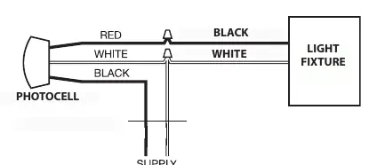
- Install the photocell and wire it according to the provided diagram.
- Ensure the photocell is rated for your supply voltage.
0-10V Dimmable Wiring
The universal voltage driver permits operation at 120V through 277V, 50 or 60 Hz. For 0-10V dimming, follow these wiring directions:
- Connect the black fixture lead to the (+) LINE supply lead.
- Connect the white fixture lead to the (-) COMMON supply lead.
- Connect the GROUND wire from the fixture to the supply ground. Do NOT connect the GROUND of the dimming fixture to the output.
- Connect the purple fixture lead to the (V+) DIM lead.
- Connect the pink (or gray) fixture lead to the (V-) DIM lead.
- Cap the yellow fixture lead, if present. Do NOT connect.
Cleaning & Maintenance
Ensure the fixture temperature is cool enough to touch before performing maintenance. Do not clean or maintain while the fixture is energized.
- Clean the glass lens with a non-abrasive glass cleaning solution.
- Do not open the fixture to clean the LED. Do not touch the LED.
Troubleshooting
- Check that the line voltage at the fixture is correct.
- Ensure the fixture is grounded properly.
- If a photocell is used, verify it is functioning properly.
Practical help
Common problems
Fixture does not turn on
Check that the line voltage at the fixture is correct and verify that the fixture is grounded properly.
Photocell not working
Verify the photocell is functioning properly and is rated for your supply voltage.
Before use
- Ensure power is OFF before installation.
- Verify mounting surface is suitable for the fixture.
- Ensure all gaskets are seated properly.
- Apply weatherproof silicone sealant to all unused conduit entries.
- Verify supply voltage matches the fixture requirements.
Specs in practice
- Universal Voltage
- Permits operation at 120V through 277V, 50 or 60 Hz.
- 0-10V Dimming
- Requires specific wiring: Purple for V+ DIM, Pink/Gray for V- DIM.
Images and diagrams
- Junction Box Mount: Illustrates the assembly of the Back Box, Housing, and Door.
- Surface Mount: Shows the Crossbar installation for recessed boxes.
- Wiring Diagrams: Provides clear connection paths for 0-10V dimming and photocell integration.
Model compatibility
- Mounting: Compatible with both conduit junction boxes and recessed junction boxes.
- Photocell: Must be rated for the supply voltage.

Manual page author
David Miller
Documentation analyst
Organizes user manual content into clear summaries, with attention to model details, product context, and everyday usability.