Lighting / LED Drivers
Installation Guide for Tivoli Infinity Direct Multi-Circuit 192 Driver
A comprehensive installation guide for the Tivoli Infinity Direct Multi-Circuit 192 Driver (Model INF-DR-J-192-2-4-24). Includes mounting requirements, wiring instructions for TRIAC and 0-10V dimming, safety warnings, and technical...
Table of contents
Manual images
Click an image to enlargeQuick Guide from the Manual
This document provides installation instructions for the Tivoli Infinity Direct Multi-Circuit 192 Driver. Before starting, ensure the power is turned off. The unit is designed for 100-277V AC input and is suitable for dry, damp, and wet locations. Always consult local and national electrical codes before installation. The unit should be installed by a certified professional.
Product Specifications
- Input: Universal 100-277VAC
- Output: Constant Voltage
- Dimming Options: ELV, MLV, TRIAC, 0-10V, and PWM
- Protection: Short circuit, Overload, and Overheat protection
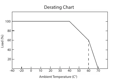
- Operating Temperature: -40°C to +60°C (with derating)
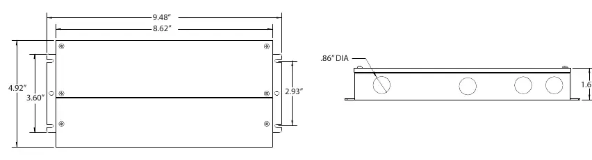
- Wire Gauges: Input 18AWG, Output 16AWG
Mounting Location Requirements
For proper ventilation and longevity, the enclosure requires at least 10 inches of open space around it. Do not mount the unit next to or above heat-radiating equipment. Refer to the derating chart in the manual if operating in high ambient temperatures.
Outdoor Installation
- Locate a suitable outdoor location.
- Mount the case vertically with the knockouts facing the bottom of the box.
- Attach the enclosure to a rigid surface using 4 screws (not provided).
- Knock out access holes as needed.
- Install strain reliefs (wire clamps) for 1/2 inch hole size.
Indoor Installation
The unit can be installed vertically, horizontally, or horizontally face-down for ceiling applications.
Connection Instructions
Open the wire compartment and remove knockouts for input and output. Install strain reliefs.
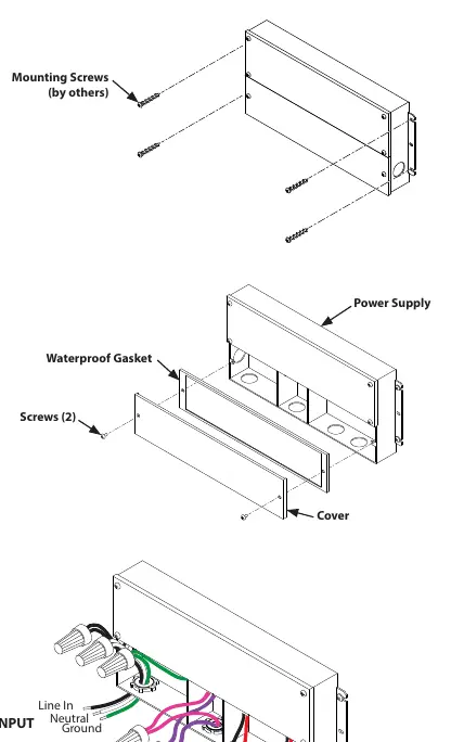
Input Connection
Bring Positive (Black) and Negative (White) power lines through the strain relief on the input side. Connect to the driver leads using UL-approved wire nuts. Connect the Ground wire (Green) to a suitable ground.
Output Connection
Bring luminaire wires through the strain relief on the output side. Connect to the Red (+), Black (-), Purple (D+), and Pink (D-) driver leads using UL-approved wire nuts. Ensure all connections are tight. The model supports up to two output circuits.
Wiring Diagrams
The manual provides specific wiring diagrams for:
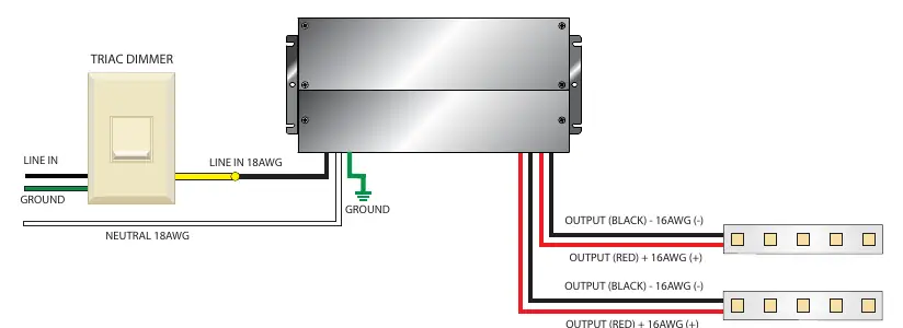
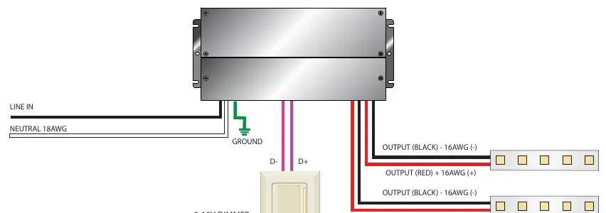
- TRIAC Primary Dimming: Connects Line, Neutral, and Ground to the input, and output leads to the luminaire.
- 0-10V Secondary Dimming: Includes connections for D- and D+ dimming control lines.
Always refer to the specific wiring diagram provided by the manufacturer of your dimmer, as wiring may vary.
Safety Warnings
- Risk of electrical shock and energy hazard.
- Do not open the case of the power supply module.
- Do not install in places with high ambient temperature or close to a fire source.
- Do not conceal or extend exposed conductors through a building wall.
Practical help
Common problems
Unit not working or damaged
Ensure input voltage is 100-277V AC. Using other power sources will cause damage and void the warranty.
Overheating
Ensure at least 10 inches of open space around the enclosure for proper ventilation.
Dimming issues
Ensure all connections are tight and wiring matches the specific dimmer manufacturer's diagram.
Before use
- Verify package contents.
- Ensure power is turned off before installation.
- Confirm mounting surface is rigid.
- Check that the location is suitable for the driver's rating (Dry/Damp/Wet).
- Ensure you have the correct size UL-approved wire nuts.
Specs in practice
- Input Voltage
- 100-277V AC line voltage.
- Operating Temperature
- -40°C to +60°C; derating required at higher temperatures.
- Output Wire Gauge
- 16AWG.
- Input Wire Gauge
- 18AWG.
Images and diagrams
- The derating chart illustrates the relationship between ambient temperature and load percentage to ensure power supply longevity.
- Wiring diagrams show the correct connection points for Line, Neutral, Ground, and Dimming control lines.
Model compatibility
- Supports up to two output circuits.
- Suitable for Dry, Damp, and Wet locations.

Manual page author
David Miller
Documentation analyst
Organizes user manual content into clear summaries, with attention to model details, product context, and everyday usability.