Garden / Garden Structures
Assembly Instructions for Toolport Polytunnel FGWH-L1-Q1 4m x 10m
Assembly guide for the Toolport Polytunnel 4m x 10m (FGWH-L1-Q1). Includes a comprehensive parts list, step-by-step construction sequence, and component identification for the frame and cover installation.
Table of contents
Manual images
Click an image to enlargeQuick guide from the manual
This document provides the assembly instructions for the Toolport Polytunnel 4m x 10m. Before beginning, ensure you have all parts listed in the inventory. The assembly process involves constructing the frame arches, connecting them with horizontal bars, securing the base, and finally attaching the cover.
Parts list
The kit includes various metal tubes, bolts, nuts, and clips. Key components include:
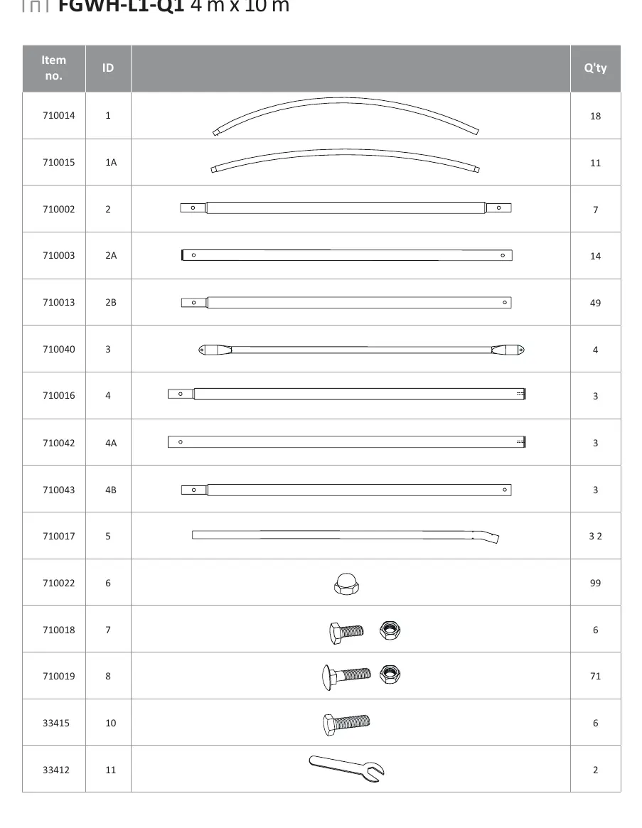
- Arches: Identified by IDs 1, 1A.
- Horizontal bars: Identified by IDs 2, 2A, 2B, 3, 4, 4A, 4B, 5.
- Fasteners: Bolts (IDs 7, 8, 10), Nuts (ID 6), and various clips/brackets (IDs 13, 14, 15).
- Tools: Wrench (ID 11) is included.
Assembly steps
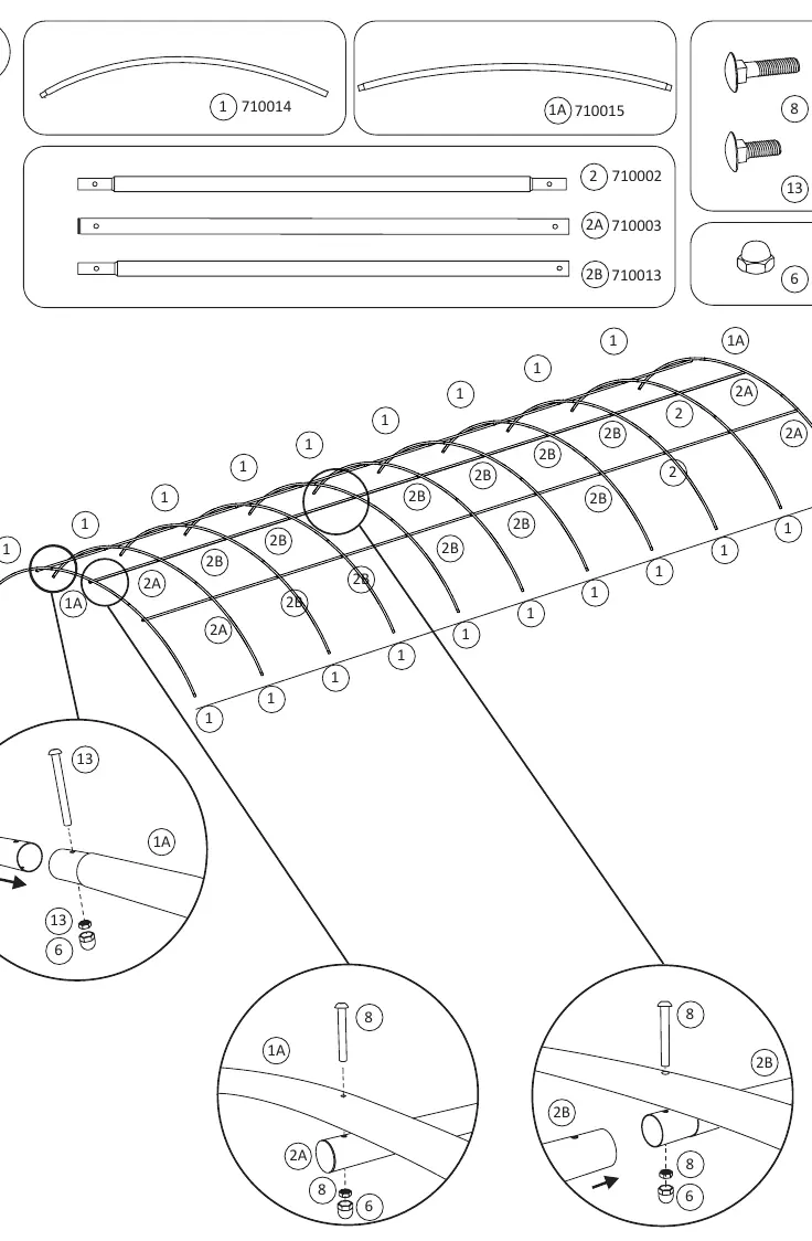
Step 1: Frame arches
Assemble the individual arches using tubes 1, 1A, 2, 2A, and 2B. Secure connections using bolts (8) and nuts (6). Use clips (13) where indicated in the diagram.
Step 2: Connecting arches
Connect the assembled arches using horizontal bars (3, 5, 2, 2A, 2B). Secure the joints with bolts (8) and nuts (6).
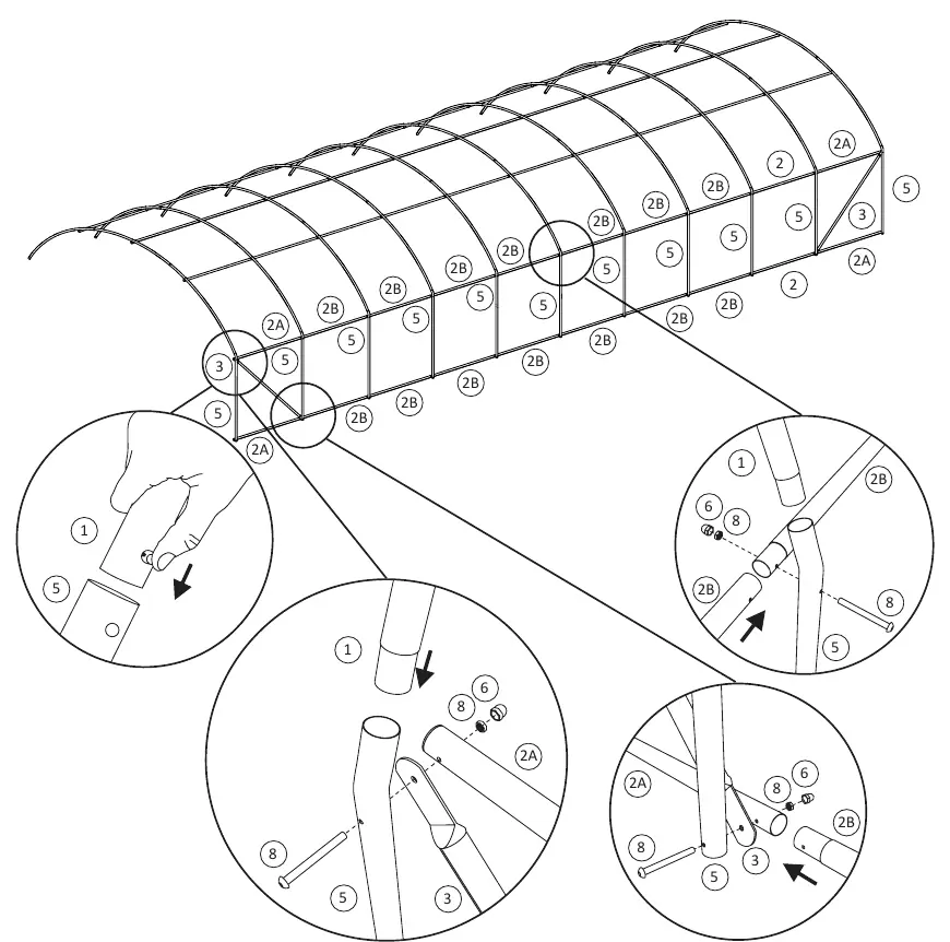
Step 3: Frame completion
Continue connecting the remaining arches and horizontal bars to form the full length of the tunnel structure.
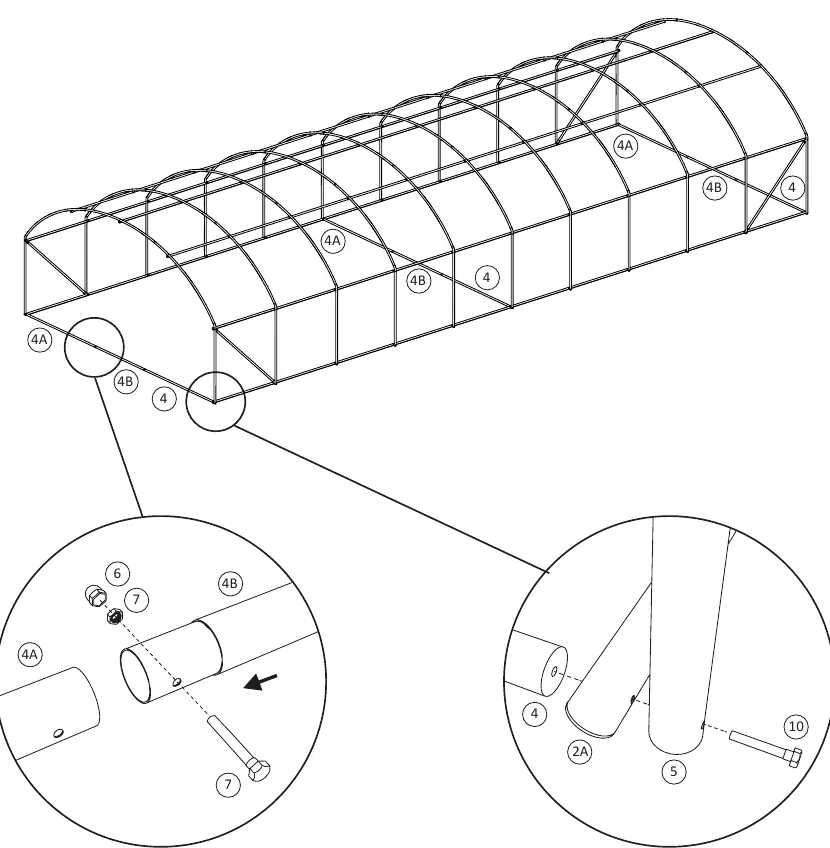
Step 4: Base and support bars
Install the base support bars (4, 4A, 4B) along the bottom of the structure. Secure using bolts (7, 10) and nuts (6).
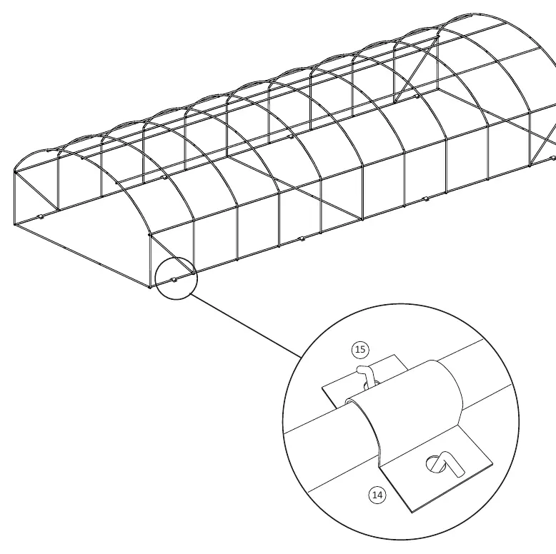
Step 5: Securing the frame
Attach the remaining clips (14) and support rods (15) to reinforce the structure.
Step 6: Covering
Install the cover (12) over the completed frame structure.
Practical help
Common problems
Missing parts
Verify all items against the parts list on pages 4 and 5 before starting assembly.
Difficulty connecting tubes
Ensure the correct ID tubes are used for each section as shown in the assembly diagrams.
Before use
- Unpack all components and organize by ID number.
- Verify quantities of all bolts, nuts, and tubes against the parts list.
- Ensure you have a clear, level area for assembly.
- Keep the provided wrench (ID 11) accessible.
Images and diagrams
- The manual uses numbered diagrams to show the exact placement of tubes and fasteners.
- Circles with numbers indicate specific parts (e.g., 2B, 8, 6) to be used at that connection point.

Manual page author
David Miller
Documentation analyst
Organizes user manual content into clear summaries, with attention to model details, product context, and everyday usability.