Electronics / Televisions
Service Manual for Toshiba 21N21E2 Colour Television
Comprehensive service manual for the Toshiba 21N21E2 colour television. Includes safety notices, disassembly instructions, electrical adjustment procedures, schematic diagrams, and parts lists for professional repair.
Quick answers from the manual
Quick answer
- This is a service manual for the Toshiba 21N21E2 colour television, containing technical specifications, safety notices, disassembly instructions, electrical adjustment procedures, and parts lists. p. 1, 3
Key actions
- Enter Service Mode p. 12
Problems and fixes
Insulation resistance low
If resistance is less than 1M ohm, inspection repair is required.
p. 2Show 3 more answers Show less
Maintenance and reset
- Factory initialization p. 12
Technical specifications
| Parameter | Value | Meaning | Pages |
|---|---|---|---|
| Power Consumption | 60 W | Power consumption at AC 230V 50Hz | p. 4 |
Where to find it in the PDF
- Servicing Notices p. 2
- General Specifications p. 4, 5, 6, 7
- Disassembly Instructions p. 9, 10, 11
- Electrical Adjustments p. 13, 14, 15, 16
- Parts Lists p. 31, 32, 33, 34
Table of contents
Manual images
Click an image to enlargeImportant Information from the Manual
This document is a professional service manual intended for qualified technicians. It contains critical safety notices, electrical adjustment procedures, and mechanical disassembly instructions for the Toshiba 21N21E2 colour television. Always observe safety precautions regarding high voltage and X-ray protection when servicing this unit.
Safety Notices
- High Voltage: The unit contains high voltage parts. Always discharge the anode cap potential voltage before starting work.
- X-Ray Safety: Safety is secured against X-rays by the cathode-ray tube and high voltage peripheral circuits. Use designated parts and do not modify these circuits.
- Insulation Check: After servicing, confirm insulation resistance between the AC cord plug blades and external metal (antenna terminal/earphone jack) is greater than 1M ohm using a 500V insulation resistance meter.
Disassembly Instructions
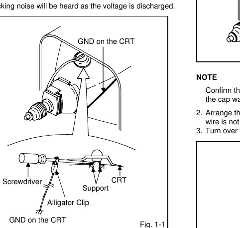
Removal of Anode Cap
- Connect an alligator clip to a flat-blade screwdriver and ground.
- While holding the plastic part of the screwdriver, touch the anode support with the tip to discharge voltage.
- Flip up the rubber cap sides and remove the support.
Removal and Installation of Flat Package IC
- Use masking tape to protect surrounding parts.
- Heat leads with a blower-type IC desoldering machine.
- Use tweezers to remove the IC once leads are desoldered.
- Use braided shield wire to absorb excess solder.
- When installing, ensure correct polarity and solder diagonal leads temporarily before soldering all pins.
Service Mode
To enter Service Mode, press both the set key and the remote control key for more than 2 seconds. Available modes include:
- 0: Reset user settings (Picture, Volume, Language).
- 1: Factory initialization (resets channel settings and power-on hours).
- 6: Display power-on total hours.
- 8: Write EEPROM initial data.
- 9: Display Adjustment Menu.
Electrical Adjustments
The manual provides detailed procedures for:
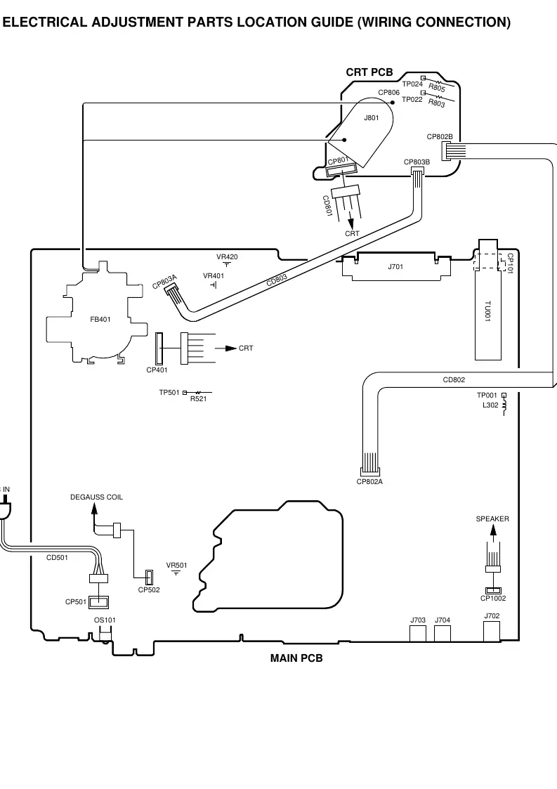
- Constant Voltage: Adjust VR501 to 117V ± 1.0V.
- VCO and AGC: Specific oscillator frequencies and voltage targets are provided for tuning.
- Focus: Adjust focus volume until the picture is distinct.
- White Balance: Adjust R Drive, G Drive, and Cutoff settings.
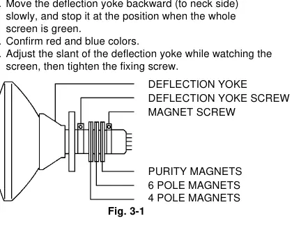
- Purity and Convergence: Procedures for static and dynamic convergence using magnets and deflection yoke adjustments.
Parts Ordering
When ordering parts, provide the Model Number (found on the back of the product) and the Version Letter (found at the end of the serial number), along with the Part Number and Description from this manual.
Practical help
Common problems
High voltage hazard
Always discharge the anode cap potential voltage before servicing.
IC replacement damage
Use only specified silicon grease (YG6260M) and remove old grease before applying new. Do not damage PCB foil.
Insulation failure
If insulation resistance is less than 1M ohm, inspection repair is required.
Before use
- Use an isolation transformer when performing service.
- Discharge the anode cap before removing it.
- Check insulation resistance after servicing.
- Use specified silicon grease for IC/transistor replacement.
- Ensure all wires are returned to original positions after assembly.
Show more Show less
Specs in practice
- Power Source
- 230V-240V AC 50Hz
- Power Consumption
- 60W (Typical)
Images and diagrams
- Wiring connection guide (Page D-5)
- Block diagram (Page E-1)
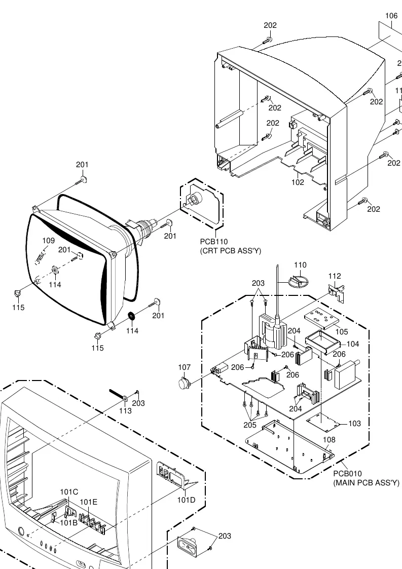
- Mechanical exploded view (Page I-1)
Model compatibility
- Designed for PAL/SECAM color systems.
- Tuner supports CCIR System B/G, D/K, I.

Manual page author
Michael Turner
Technical manual editor