Computers / Storage
Installation Manual for Toshiba Floor Standing Air Conditioner RAV-HM Series
Professional installation guide for Toshiba RAV-HM series floor-standing air conditioners. This manual covers safety precautions, mounting instructions, refrigerant piping, electrical wiring, system setup, and troubleshooting.
Quick answers from the manual
Quick answer
- This manual provides installation, wiring, and maintenance instructions for the Toshiba RAV-HM series floor-standing air conditioners. It emphasizes safety, proper refrigerant handling (R32), and electrical connection procedures. p. 1, 58, 64, 67
Key actions
- Installation must be performed by a qualified installer. p. 3, 5
- Perform an airtight test using nitrogen gas after piping. p. 6, 64
First start
- After power-on, it takes approximately 5 minutes for the remote controller to become available. p. 68
Problems and fixes
E18 error code
Check wiring between header and follower units; ensure no wire is connected between ③-③.
p. 66, 73Error codes
| Code | Meaning | Action | Pages |
|---|---|---|---|
| E01 | No header remote controller / Remote controller communication trouble | Check remote controller settings and wiring. | p. 76 |
| P01 | Indoor unit fan trouble | Check fan motor and thermal relay. | p. 77 |
Maintenance and reset
- Reset the filter sign via the remote controller menu after cleaning. p. 74
Technical specifications
| Parameter | Value | Meaning | Pages |
|---|---|---|---|
| Insulation Resistance | 1 MΩ or more | Required resistance between charge section and earth. | p. 7, 72 |
Where to find it in the PDF
- Safety Precautions p. 4, 5, 6, 7
- Installation p. 58, 59, 60
- Electrical Connection p. 65, 66, 67
- Troubleshooting p. 76, 77
Table of contents
Manual images
Click an image to enlargeImportant Safety Information
This manual is intended for qualified installers and service personnel. The air conditioner uses R32 refrigerant, which requires specific handling. Always wear protective gear, including gloves and safety clothing, during installation and maintenance. Ensure the circuit breaker is set to OFF before performing any work. The unit must be installed in a location that can support its weight and complies with minimum floor area requirements to prevent refrigerant concentration issues in case of a leak.
Installation Overview
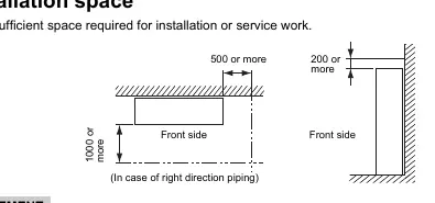
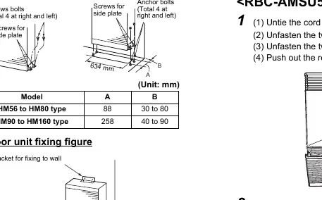
The unit is designed for floor standing installation. Ensure sufficient space is reserved for maintenance and airflow. The unit must be fixed securely to both the wall and the floor using the provided brackets. For high-humidity environments, attach the heat insulator to the side and rear of the unit.
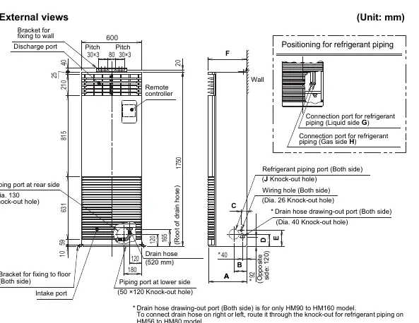
Refrigerant Piping
Use seamless phosphorous deoxidized copper pipes. Ensure all flare connections are tightened to the specified torque using a torque wrench. After installation, perform an airtight test using nitrogen gas and check for leaks. Evacuate the system using a vacuum pump before opening the valves.
Electrical Wiring
Electrical work must be performed by qualified personnel in accordance with local regulations. Connect the earth wire securely. Do not connect the power supply or indoor/outdoor connecting wires in the middle. Use a circuit breaker that meets the specifications provided in the manual.
Troubleshooting
If a check code appears on the remote controller, refer to the troubleshooting section. Common issues include wiring errors (E18), fan motor trouble (P01), or refrigerant leak detection (J30). Do not attempt to repair the unit yourself if a serious error occurs; contact a qualified service person.
Maintenance
Regular maintenance is recommended to ensure efficient operation. Clean the air filter periodically. If the filter sign appears, clean the filter and reset the sign via the remote controller. Inspect the heat exchanger, fan, and drain pan for dust, dirt, or damage.
Practical help
Common problems
Check code E18
Indicates a communication error between header and follower units. Check wiring connections between indoor units.
Refrigerant leak detected
The refrigerant leak detection sensor has triggered. Contact a service technician immediately.
Unit not cooling or heating
Check for error codes on the remote controller, ensure the circuit breaker is ON, and verify that the outdoor unit valve is fully open.
Before use
- Ensure the circuit breaker is ON.
- Verify that the electrical control box cover and service panels are closed.
- Check that the refrigerant piping is connected and leak-tested.
- Confirm insulation resistance is 1 MΩ or more.
- Ensure the drain hose is properly connected and sloped.
- Reset the filter sign after cleaning.
Specs in practice
- R32 Refrigerant
- HFC refrigerant used in this unit; requires special tools and handling.
- Insulation Resistance
- Must be 1 MΩ or more between the charge section and earth to prevent electric shock.
Images and diagrams
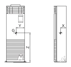
- Center of gravity diagram: Shows the X, Y, Z coordinates for lifting and positioning the unit.
- Installation space: Provides minimum clearance dimensions (mm) for front and side access.
- Wiring diagram: Illustrates connections between indoor and outdoor units and the remote controller.
Model compatibility
- Requires a wired remote controller for system status display.
- Indoor units must be installed in the same room for simultaneous twin/triple systems.
- Use only R32-compatible tools.

Manual page author
David Miller
Documentation analyst
Organizes user manual content into clear summaries, with attention to model details, product context, and everyday usability.