Electronics / Networking
TP-Link LS105LP/LS106LP/LS109P Desktop PoE+ Switch Installation Guide
A comprehensive installation guide for TP-Link LS105LP, LS106LP, and LS109P Desktop PoE+ Switches. Includes connection diagrams, LED status explanations, PoE feature configuration (Extend, Isolation, Auto Recovery), and troubleshooting...
Table of contents
Quick Guide
This guide covers the installation and operation of the TP-Link LS105LP, LS106LP, and LS109P Desktop PoE+ Switches. Key features include PoE+ support, Extend mode for long-distance transmission, and PoE Auto Recovery. Ensure your power source meets the switch requirements and that Ethernet cables are within the specified length limits (100m standard, 250m in Extend mode).
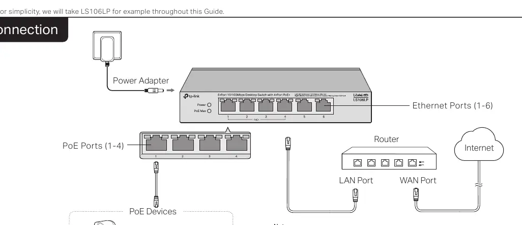
Connection
To set up the switch, connect the power adapter to the switch and a power outlet. Connect your router to the uplink port (or a standard port) and connect your PoE devices (such as IP cameras, access points, or IP phones) to the PoE ports. Note that PoE ports can also connect to non-PoE devices for data transmission only.
LED Explanation
The LEDs provide real-time status of the switch:
- Power: On indicates the switch is powered on.
- PoE Status: On indicates the port is providing PoE power; Flashing indicates a current overload or short-circuit.
- Link/Act: On indicates a link at 10/100 Mbps; Flashing indicates data transmission.
- PoE Max: Indicates the total power supply status. Flashing indicates the total power supply is at or above the threshold (41W for LS105LP/LS106LP, 63W for LS109P).
Switch Features
The switch includes specific modes to enhance functionality:
- Extend (LS105LP/LS106LP/LS109P): When enabled, ports run at 10 Mbps and support PoE power supply up to 250 meters away.
- Isolation (LS109P only): When enabled, ports cannot communicate with other downlink ports, only with the uplink port.
- Recovery (LS105LP/LS106LP/LS109P): When enabled, the switch constantly monitors the PoE powered device. If the device stops responding, the switch will automatically reboot it.
Troubleshooting
If you encounter issues, check the following:
- Power LED not lit: Ensure the power cord is connected properly and the power source is active.
- Link/Act LED not lit: Verify cable connections, ensure the connected device is powered on, and check that the cable length is within limits (100m or 250m if Extend mode is on).
- PoE ports not supplying power: If total power consumption exceeds the maximum, the switch prioritizes lower port numbers and may cut power to higher-numbered ports.
Specifications
- Standards: IEEE802.3i, IEEE802.3u, IEEE802.3x, IEEE802.3af, IEEE802.3at.
- PoE Budget: 41W (LS105LP/LS106LP) or 63W (LS109P).
- Operating Temperature: 0°C to 40°C (32°F to 104°F).
- Operating Humidity: 10% to 90% RH non-condensing.
Safety Information
Keep the device away from water, fire, humidity, or hot environments. Do not attempt to disassemble, repair, or modify the device. Place the device with its bottom surface downward. Use only the provided power adapter.
Practical help
Common problems
Power LED is not lit
Check that the AC power cord is connected properly to the switch and a live power source. Verify the voltage meets the switch requirements.
Link/Act LED is not lit
Ensure cable connectors are firmly plugged in, the connected device is turned on, and the cable length is under 100m (or 250m if Extend mode is enabled).
PoE ports not supplying power
The total power consumption may exceed the PoE budget. The switch prioritizes lower port numbers; it may cut power to higher-numbered ports to maintain operation for others.
Before use
- Ensure the power adapter is connected to a stable power source.
- Verify that Ethernet cables are within the 100m limit (or 250m if Extend mode is active).
- Check that connected PoE devices are compatible with the switch's PoE standards.
- Ensure the device is placed on a flat surface with the bottom facing down.
Specs in practice
- PoE Auto Recovery
- Automatically reboots a connected PoE device if it stops sending data packets.
Images and diagrams
- The connection diagram illustrates the switch connected to a power adapter, a router via the uplink port, and various PoE devices (IP Camera, AP, IP Phone) via PoE ports 1-4.
Model compatibility
- PoE ports can connect to non-PoE devices for data transmission only.
- LS109P includes a dedicated uplink port for connecting to routers.

Manual page author
Michael Turner
Technical manual editor
Reviews PDF manuals for structure, safety notes, and practical product details so readers can find the right information quickly.