Lighting / LED Drivers
User Manual for Sigor 9057801 DALI 100W LED Driver
Quick guide for the Sigor 9057801 DALI 100W LED Driver. Includes wiring diagrams, operation modes (DALI and Push Dim), technical specifications, and safety instructions.
Table of contents
Manual images
Click an image to enlargeQuick Guide
The Sigor 9057801 is a 100W DALI DT8 LED driver designed for 24V DC constant voltage output. It supports both DALI bus control and Push Dimming. Ensure all installations are performed by qualified personnel and read all instructions prior to installation.
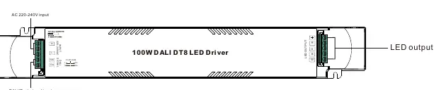
Product Overview
This device is a 4-channel LED driver compatible with universal DALI masters that support DT8 commands. It features smooth, deep dimming down to 0.1% and includes an error report function.
Technical Specifications
- Rated Power: Max. 100W
- Output: 24V DC, 4 Channels (Max 4.17A total)
- Input Voltage: 220-240V AC, 50/60Hz
- Dimming Interface: DALI DT8 / Push
- Dimming Range: 0.1% - 100%
- Protection: Over Voltage, Over Load, Short Circuit, Over Temperature (all automatic recovery)
- IP Rating: IP20 (Indoor use only)
Safety & Warnings
- DO NOT expose the device to moisture.
- DO NOT install with power applied to the device.
- Ensure the total load does not exceed 100W.
- The device is intended for indoor LED lighting applications.
Operation
DALI Address
1 DALI address for 4 channels output is assigned by the DALI Master controller automatically. Please refer to the user manuals of compatible DALI Masters for specific operations.
PUSH Dimmer Mode
When connected with an AC PUSH button, the driver operates in Push Dimmer Mode:
- Switch ON/OFF: Click the button.
- Adjust Intensity: Press and hold the button to increase or decrease light intensity to the desired level, then release. Repeat the operation to adjust in the opposite direction.
- Memory Function: The device memorizes the status before power off and restores it when powered on again.
Wiring Diagrams
The device supports two primary wiring configurations:
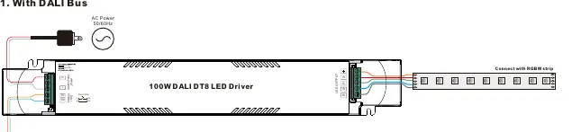
- DALI Bus: Connect the DALI signal lines to the DA/DA terminals and the AC power to the L/N terminals.
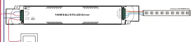
- Push Dim: Connect the push-button switch to the PUSH DIM terminal and the AC power to the L/N terminals.
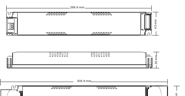
Dimensions
The unit measures 306.6mm x 43mm x 30mm (L x W x H).
Practical help
Common problems
Light does not dim or respond to commands
Verify that the DALI master is compatible with DT8 commands or check that the Push Dim wiring is secure.
Device does not turn on
Check the AC power supply (220-240V) and ensure all connections are tight.
Before use
- Verify input voltage is 220-240V AC.
- Ensure the LED strip is 24V DC.
- Check that the total load does not exceed 100W.
- Ensure the installation environment is dry (IP20 rating).
- Confirm the DALI master supports DT8 commands if using DALI control.
Images and diagrams
- Wiring Diagram 1: Shows connection for DALI Bus control.
- Wiring Diagram 2: Shows connection for Push Dim control.
Model compatibility
- Compatible with universal DALI masters supporting DT8 commands.
- Requires 24V DC constant voltage LED strips.

Manual page author
Michael Turner
Technical manual editor
Reviews PDF manuals for structure, safety notes, and practical product details so readers can find the right information quickly.