Sports / Fitness
User Manual for Sunny Health & Fitness SF-B0891 Under Desk Magnetic Cycle
Quick guide for the Sunny Health & Fitness SF-B0891 Under Desk Magnetic Cycle. Includes assembly instructions, meter operation, tension adjustment, and safety warnings.
Table of contents
Manual images
Click an image to enlargeQuick Start Guide
Before using your Sunny Health & Fitness SF-B0891, please note the following critical information:
- Do not stand on the unit. This equipment is designed for use in a sitting position only.
- Remove the plastic tab from the meter before first use to activate the battery.
- Ensure the unit is placed on a solid, flat surface with at least 60 cm (2 feet) of free space around it.
- Check that all nuts and bolts are securely tightened before use.
Safety Information
Safe and effective use requires proper assembly and maintenance. Please adhere to these guidelines:
- Consult a physician before starting any exercise program.
- Keep children and pets away from the equipment.
- Wear suitable clothing; avoid loose items that could get entangled.
- Do not place fingers or objects into moving parts.
- The equipment is for indoor, home use only and is not suitable for therapeutic or commercial purposes.
- If you hear unusual noises or find defective components, discontinue use immediately.
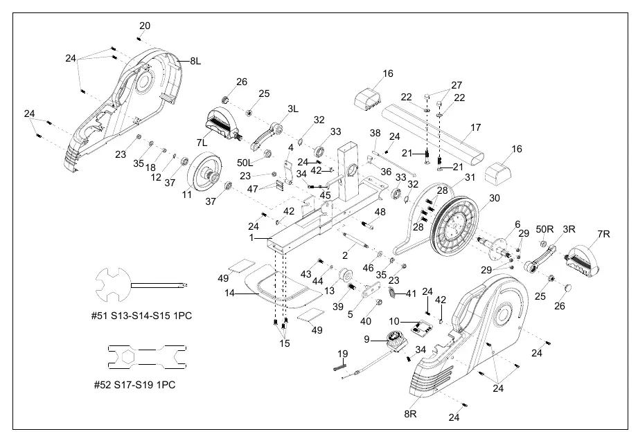
Assembly Instructions
The assembly requires the included tools (Spanner #51 and #52).
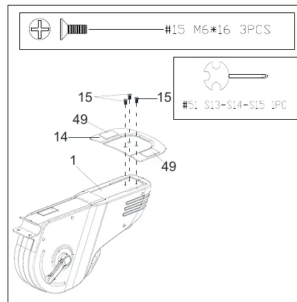
Step 1: Rear Fixed Bottom Plate
Attach the Rear Fixed Bottom Plate (No. 14) to the Main Frame (No. 1) using 3 Bolts (No. 15). Tighten securely with Spanner (No. 51).
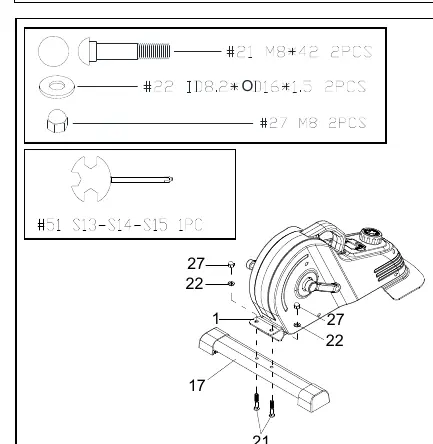
Step 2: Front Stabilizer
Attach the Front Stabilizer (No. 17) to the Main Frame (No. 1) using 2 Carriage Bolts (No. 21), 2 Washers (No. 22), and 2 High Cap Nuts (No. 27). Tighten securely with Spanner (No. 51).
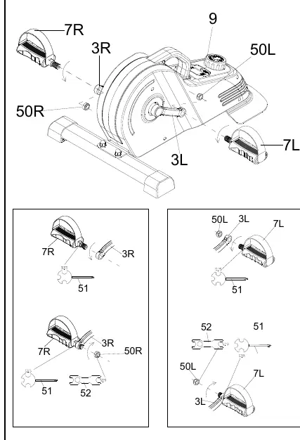
Step 3: Pedals
Note that pedals are marked 'L' (Left) and 'R' (Right). Left Nylon Nut (No. 50L) is blue inside; Right Nylon Nut (No. 50R) is white inside.
- Remove the 2 Nylon Nuts (No. 50L & 50R) from the pedals.
- Align the Left Pedal (No. 7L) with the Left Crank (No. 3L) at 90°. Insert and turn counter-clockwise by hand, then tighten with Spanner (No. 51).
- Secure the Left Nylon Nut (No. 50L) clockwise using Spanner (No. 51) to hold the bolt and Spanner (No. 52) to turn the nut.
- Repeat the process for the Right Pedal (No. 7R) and Right Crank (No. 3R), turning the pedal clockwise and the nut counter-clockwise.
Exercise Meter
The meter tracks your workout progress.
Functions
- SPEED: Displays current speed.
- TIME: Counts total exercise time.
- DIST (DISTANCE): Counts total distance.
- CAL (CALORIES): Counts total calories burned.
- SCAN: Automatically cycles through TIME, CALORIES, and DISTANCE.
The meter powers on automatically when pedals move or the MODE key is pressed. It shuts off after 4-5 minutes of inactivity.
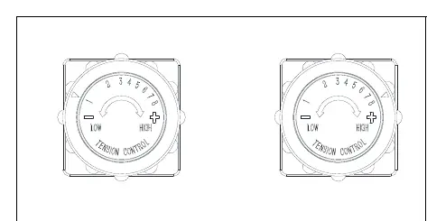
Adjustments and Usage
Adjust the resistance by rotating the Tension Control Knob (No. 9). Turn clockwise to increase resistance (Level 8 is highest) and counter-clockwise to decrease resistance (Level 1 is lowest).
Battery Installation and Replacement
The meter uses one LR44 1.5V button cell battery.
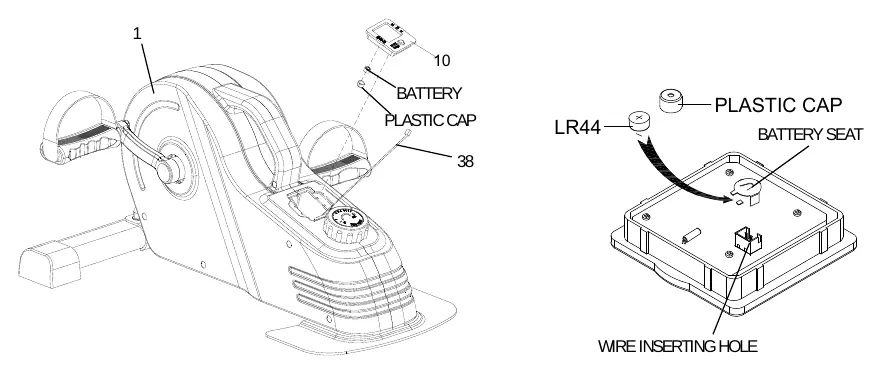
- Remove the Meter (No. 10) from the Main Frame (No. 1).
- Disconnect the link wire of the Inductor (No. 38).
- Remove the plastic cap from the back of the meter.
- Insert the battery with the positive (+) side facing upward.
- Replace the plastic cap, reconnect the link wire, and reattach the meter to the frame.
Practical help
Common problems
Abnormal display on the meter
Replace the LR44 1.5V battery.
Unusual noises during exercise
Discontinue use immediately, check for defective components, and ensure all bolts are tightened.
Before use
- Remove the plastic tab from the meter.
- Ensure the unit is on a solid, flat surface.
- Verify at least 60 cm (2 feet) of free space around the unit.
- Check that all nuts and bolts are securely tightened.
- Wear suitable, non-loose clothing.
Specs in practice
- Tension Levels
- Adjustable from 1 (lowest) to 8 (highest) using the Tension Control Knob.
- Battery Type
- LR44 1.5V button cell battery.
Images and diagrams
- Exploded Diagram: Use to identify parts by number for replacement or assembly.
- Hardware Package: Shows the specific bolts, nuts, and washers required for assembly steps.
Model compatibility
- Indoor and home use only.
- Not for commercial or therapeutic use.
- Use only in a sitting position.

Manual page author
Emily Carter
User documentation editor
Prepares concise manual descriptions and highlights the most useful setup, operation, and maintenance information for readers.