Lighting / Fixtures
User Manual for Uolfin 5069513 3-Light Fixture
Quick guide for installing and maintaining the Uolfin 5069513 3-light fixture. Includes wiring instructions, safety warnings, and assembly steps.
Quick answers from the manual
Quick answer
- This manual provides instructions for installing the Uolfin 5069513 3-light fixture, including wiring, assembly, and safety precautions. p. 1, 2, 3
Key actions
- Turn off electricity before starting p. 1, 2
- Connect ground wire to bare copper wire p. 3
Problems and fixes
Back plate not snug against wall
Adjust the threaded length of the pre-assembled mounting screws on the mounting plate.
p. 3Show 3 more answers Show less
Maintenance and reset
- Clean fixture with soft cloth and mild soap p. 3
Technical specifications
| Parameter | Value | Meaning | Pages |
|---|---|---|---|
| Max Wattage | 40W | Per bulb | p. 1 |
| Voltage | 120V | Operating voltage | p. 1 |
Where to find it in the PDF
- Safety and Tools p. 1
- Parts and Assembly p. 2
- Wiring and Finishing p. 3
Table of contents
Manual images
Click an image to enlargeImportant Information
This manual provides instructions for the installation and maintenance of the Uolfin 5069513 3-light fixture. It is recommended that a licensed electrician performs the installation. Always ensure the power is turned off at the main circuit breaker before beginning any work.
Safety Warnings
- Voltage: Ensure the supply voltage is 120V.
- Wattage: Do not exceed 40W per bulb.
- Environment: Keep the lamp away from acidic and alkaline substances to prevent surface damage.
- Bulb Replacement: Turn off or unplug the lamp and allow bulbs to cool before replacing.
- Mounting: Ensure the ceiling or wall can support the weight of the lamp. The mounting surface should be clean, dry, flat, and at least 1/4 inch larger than the canopy.
Tools Required
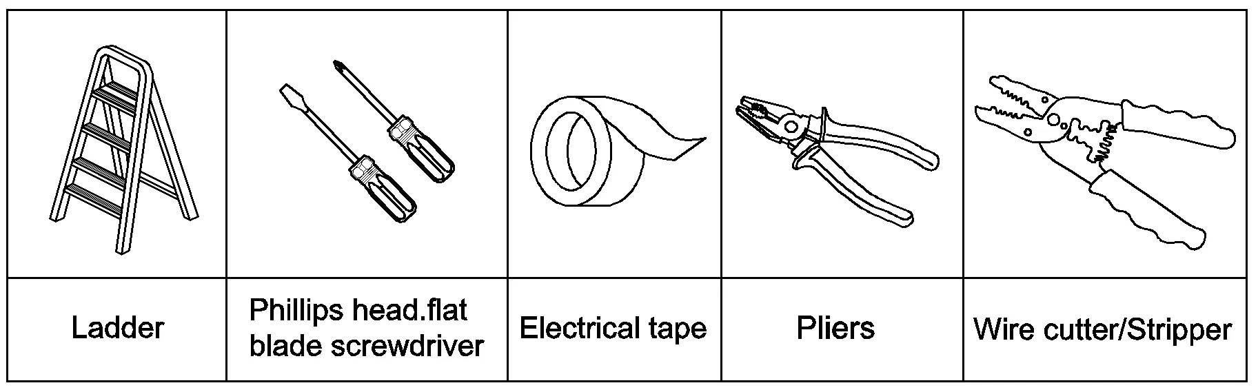
Before starting, prepare the following tools: ladder, Phillips head screwdriver, flat blade screwdriver, electrical tape, pliers, and wire cutter/stripper.
Parts List
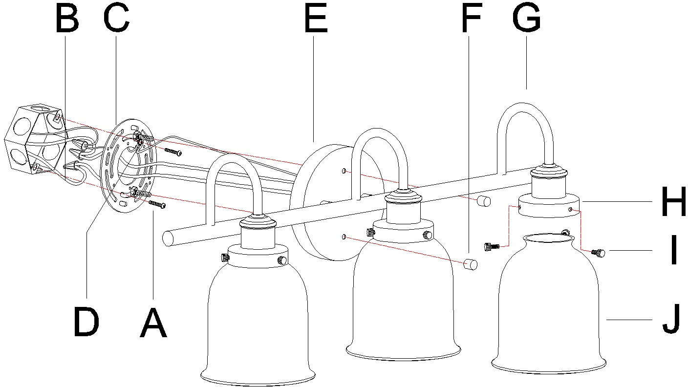
The package includes the mounting plate, green ground screw, back plate, knob nuts, arms, sockets, screws, glass shades, mounting screws, and plastic wire connectors.
Installation Steps
- Preparation: Remove the fixture from the carton and verify all parts are present. Turn off the main power.
- Mounting: Secure the mounting plate to the outlet box using the provided mounting screws.
- Wiring: Connect the fixture wires to the supply wires according to the wiring chart. Ensure the ground wire is connected to the bare copper wire. Use plastic wire connectors and electrical tape to secure connections.
- Attachment: Align the back plate with the pre-assembled mounting screws on the mounting plate and secure it using the knob nuts. If the back plate is not snug against the wall, adjust the threaded length of the mounting screws on the mounting plate.
- Finishing: Install the glass shades onto the sockets and secure them with screws. Install the bulbs (not included).
Wiring Guide
Connect the supply wires to the fixture wires as follows:
- Black or Red Supply Wire: Connect to the black fixture wire (or parallel cord round/smooth, or clear/brown/gold/black without tracer).
- White Supply Wire: Connect to the white fixture wire (or parallel cord square/ridged, or clear/brown/gold/black with tracer).
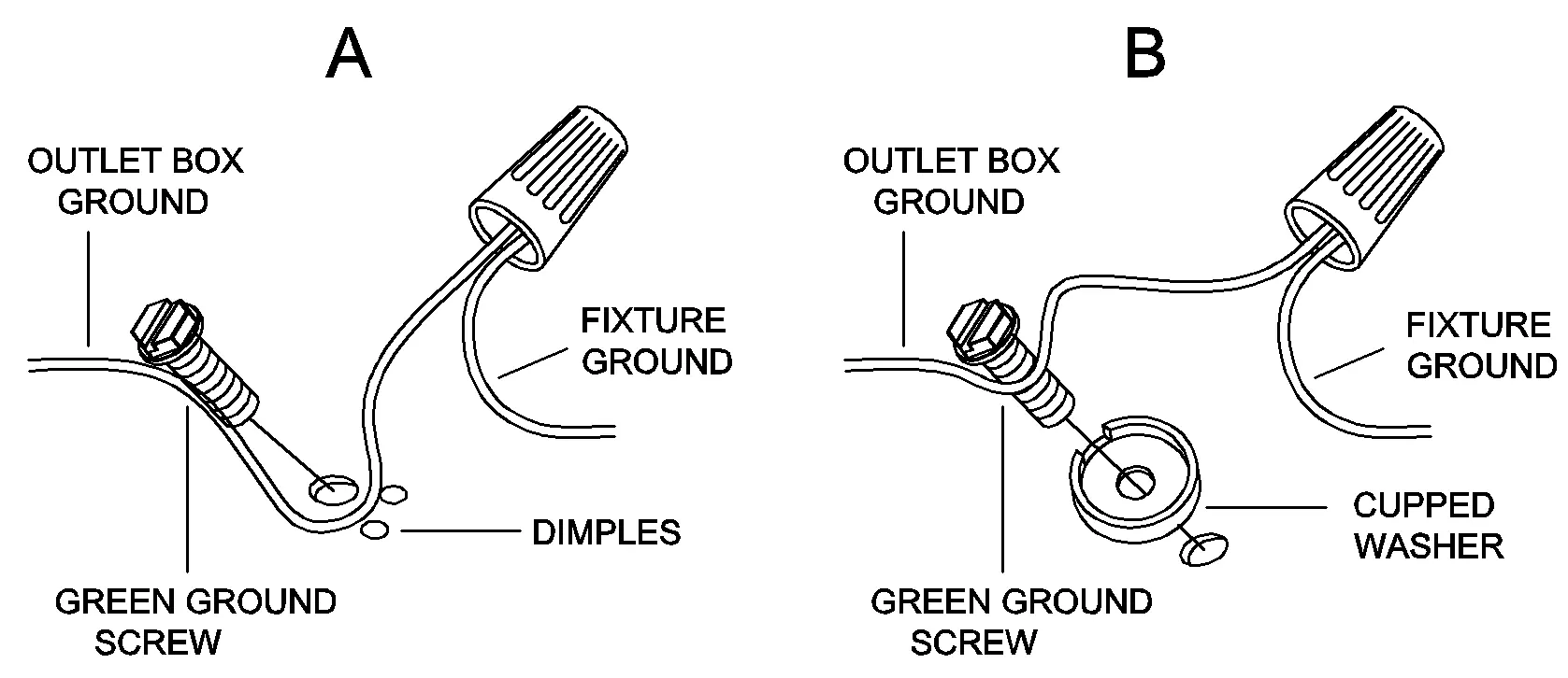
- Ground Wire: Connect the fixture ground wire to the outlet box ground wire using the green ground screw.
Cleaning and Maintenance
Wipe the fixture with a soft cloth. Clean the glass using a mild cleaner, such as mild, non-abrasive soap. Do not use abrasive materials like scouring pads, powders, steel wool, or abrasive paper.
Practical help
Common problems
Back plate is not snug against the wall
Remove the back plate, adjust the threaded length of the pre-assembled mounting screws on the mounting plate by unscrewing the hex nuts, and then screw the mounting screws in or out until the secure length is achieved.
Before use
- Turn off main power at the circuit breaker
- Ensure mounting surface is clean, dry, and flat
- Verify voltage is 120V
- Check that ceiling/wall can support the lamp weight
- Prepare required tools: ladder, screwdrivers, tape, pliers, wire cutter
Show more Show less
Images and diagrams
- A1-A5 show the assembly sequence
- Wiring chart explains how to connect supply wires to fixture wires
- Grounding diagrams show proper connection to the outlet box ground

Manual page author
David Miller
Documentation analyst