Lighting / Outdoor Lighting
V-TAC LED Waterproof Fitting Installation Guide
Quick installation guide for V-TAC LED Waterproof Fitting. Includes step-by-step instructions for single and linkable unit mounting, wiring diagrams, and technical specifications.
Table of contents
Quick Guide
This guide provides essential instructions for installing the V-TAC LED Waterproof Fitting. Ensure all electrical work is performed by a qualified electrician. The product is designed for 10-12 hours of daily operation; continuous 24-hour usage will void the warranty.
Safety Warnings
- Switch off the power supply before starting any installation work.
- The light source is not replaceable; if it reaches the end of its life, the entire luminaire must be replaced.
- If the external cable is damaged, it must be replaced by the manufacturer or a qualified service agent.
- Installation must be performed by a qualified electrician.
- Risk of electric shock.
Technical Data
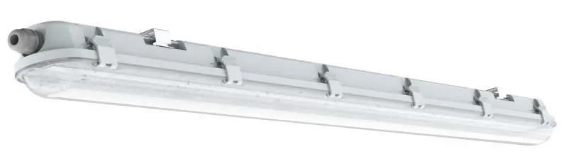
The V-TAC LED Waterproof Fitting is available in several models with varying power and dimensions:
- VT-60018: 18W, 2160LM, 600x72x78mm
- VT-120036: 36W, 4320LM, 1200x72x78mm
- VT-150048: 48W, 5760LM, 1500x72x78mm
- VT-120136-T: 36W, 4320LM, 1200x72x78mm (SS Clip)
- VT-150148-T: 48W, 5760LM, 1500x72x78mm (SS Clip)
All models feature IP65 rating, >80 CRI, >0.9 PF, 120-degree beam angle, and operate on AC 200-240V, 50/60Hz.
Installation: Single Unit
- Switch OFF the power before starting.
- Fix the mounting brackets to the ceiling using the included screws and expansion plugs. Refer to Table 1 in the manual for specific distance points.
- Mount the waterproof lamp onto the brackets.
- Open the side clips of the fitting and open the diffuser.
- Fasten the waterproof connector clockwise. Insert the cable through the connector and wire it into the terminal block (L for Live, N for Neutral).
- Install the diffuser back onto the fitting and close the clips.
- Wire the fitting to the main power supply using a waterproof terminal block (not included).
- Switch ON the power to test the light.
Installation: Multiple (Linkable) Units
Note: Check the model number to determine the maximum number of linkable units allowed.
- Switch OFF the power before starting.
- Fix the mounting brackets to the ceiling.
- Mount the waterproof lamp onto the brackets.
- Open the side clips and diffuser.
- Wiring the first unit: Fasten the waterproof connector clockwise at the first end. Insert the cable through the connector and wire it into the terminal block (L and N).
- Wiring subsequent units: Fasten the waterproof connector at the other end of the fitting and insert the wire into the terminal block. Use the same cable to fasten the connector of the next fitting and wire it into the terminal block.
- Install the diffuser and close the clips.
- Wire the final fitting to the main power supply using a waterproof terminal block (not included).
- Switch ON the power to test the light.
Warranty Information
The product is covered by a 3-year warranty from the date of purchase. The warranty does not cover damage caused by incorrect installation, abnormal wear and tear, or improper removal. Usage for 24 hours a day voids the warranty.
Practical help
Common problems
Light does not turn on after installation.
Verify that the power supply is switched on and that all wiring connections in the terminal block are secure (L and N).
Warranty is voided.
Ensure the product is not operated for 24 hours a day. The recommended daily operation is 10-12 hours.
Before use
- Ensure the power supply is switched off.
- Verify you have a waterproof terminal block (not included).
- Check the ceiling surface for mounting suitability.
- Confirm the number of linkable units does not exceed the maximum allowed for your specific model.
- Ensure you have the correct screws and expansion plugs (included).
Images and diagrams
- Step 2: Use the provided Table 1 to determine the exact distance between mounting brackets for your specific model.
- Step 5/6: Wiring requires passing the cable through the waterproof connector and securing it to the terminal block inside the fitting.
Model compatibility
- Linkable units: The maximum number of units that can be connected depends on the specific model number. Refer to the technical data table.

Manual page author
David Miller
Documentation analyst
Organizes user manual content into clear summaries, with attention to model details, product context, and everyday usability.