HVAC / Air Handlers
Operation Manual for Viessmann 5549 Universal Push-Button Panel
Quick guide for the Viessmann 5549 Universal Push-Button Panel. Learn how to install, connect, and operate this feedback-enabled control unit for model train layouts.
Quick answers from the manual
Quick answer
- The Viessmann 5549 is a push-button panel with feedback for controlling model train turnouts and signals. It requires drives with mechanical end switches to function correctly. p. 2
Key actions
- Mounting the panel p. 3
- Connecting multiple panels p. 3
Problems and fixes
Feedback function not working
Check if the connected drives have a mechanical end switch.
p. 2Technical specifications
| Parameter | Value | Meaning | Pages |
|---|---|---|---|
| Max switching current | 2 A | Maximum current capacity | p. 3 |
| Max switching voltage | 24 V AC/DC | Maximum voltage capacity | p. 3 |
Where to find it in the PDF
- Important information and Introduction p. 2
- Mounting and Connection p. 3
- Wiring Diagram p. 4
Table of contents
Manual images
Click an image to enlargeQuick guide from the manual
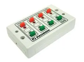
The Viessmann 5549 is a universal push-button panel with feedback, designed for controlling turnouts and signals in model train layouts. It features 8 momentary contacts arranged in 4 groups, with red and green LEDs for status feedback. Important: The feedback function only works with drives that have a mechanical end switch (e.g., Fleischmann, Roco, Märklin, or Viessmann semaphore signals). It is not compatible with digital semaphore signals or older Märklin M/K turnouts.
Installation
Mount the panel using the enclosed screws in a suitable location on your model train layout or diorama. Apply the included decal strip to the housing, ensuring the colors align correctly with the buttons as shown in the diagram.
Connection
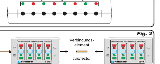
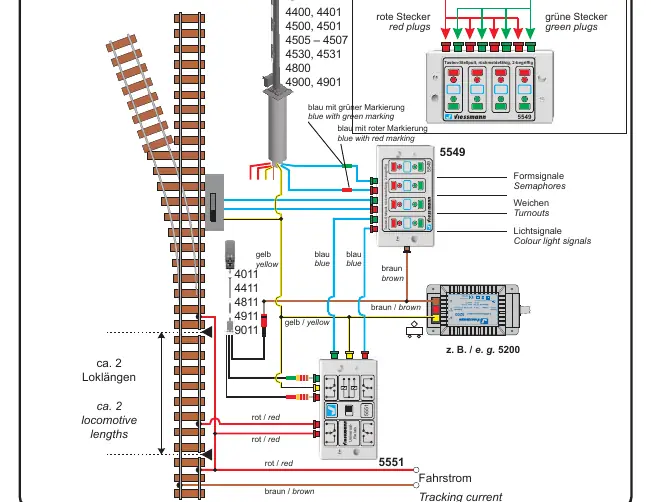
You can connect Viessmann semaphore signals directly to the panel. For light signals, a Viessmann universal relay (1 x 4UM, item 5551) is required. Multiple push-button panels can be daisy-chained together using the provided connector element.
Safety and Technical Data
Ensure all wiring is performed while the power supply is switched off. Use only VDE/EN tested model train transformers. The maximum switching current is 2 A, and the maximum switching voltage is 24 V AC/DC. The unit is intended for operation in dry rooms only.
Manufacturer information
Viessmann Climate Solutions
Practical help
Common problems
Feedback LEDs are not functioning
Ensure the connected drives have a mechanical end switch. The feedback function is not compatible with drives lacking this feature.
Cannot control light signals
Light signals require the use of a Viessmann universal relay 1 x 4UM (item 5551).
Before use
- Verify the transformer is VDE/EN tested
- Ensure power is switched off before mounting or wiring
- Check that drives have mechanical end switches
- Apply decals to the housing for color reference
Specs in practice
- Max switching current
- 2 A
- Max switching voltage
- 24 V AC/DC
Images and diagrams
- Fig 1: Button layout and color coding
- Fig 2: Connecting multiple panels together
- Fig 3: Wiring diagram for signals and turnouts
Model compatibility
- Compatible with Fleischmann, Roco, Märklin, and Viessmann drives with mechanical end switches.
- Not compatible with older Märklin M/K turnouts, digital semaphore signals, or specific hobby light signals (4021/4022).

Manual page author
Emily Carter
User documentation editor
Prepares concise manual descriptions and highlights the most useful setup, operation, and maintenance information for readers.