Toys / Model Accessories
Viessmann DLFSABH and DLFLABH Air Handler Unit Technical Data Manual
Technical data manual for Viessmann DLFSABH and DLFLABH air handler units. Includes installation guidelines, wiring diagrams, specifications, and control system details.
Quick answers from the manual
Quick answer
- The Viessmann DLFSABH/DLFLABH is a ductless air handler unit available in capacities from 1.5 to 5 tons. It supports multi-poise installation, 24V thermostat integration, and includes microprocessor-based controls. p. 1, 2, 15
Key actions
- Install the unit level in all planes for reliable operation. p. 8
- Connect power and communication wiring according to NEC/CEC codes. p. 8
First start
- Ensure all wiring is tightly connected and the unit is level. Verify thermostat compatibility. p. 8, 9
Problems and fixes
Communication interference
Use 14/2 stranded shielded cable for L2 and (S) in high EMF areas.
p. 8Technical specifications
| Parameter | Value | Meaning | Pages |
|---|---|---|---|
| Voltage | 208/230-1-60 | Power supply requirements | p. 7 |
Where to find it in the PDF
- Product Data p. 2
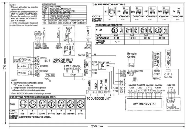
- Wiring Diagrams p. 13, 14
Table of contents
Manual images
Click an image to enlargeQuick guide from the manual
This manual provides technical data and installation guidelines for the Viessmann DLFSABH and DLFLABH air handler units. These units are designed for ductless systems, offering multi-poise installation flexibility, 24V thermostat interface compatibility, and microprocessor-based controls. Ensure all wiring complies with local codes (NEC/CEC) and that the unit is level in all planes for reliable operation.
Product Overview
The air handler units are designed for quiet, secure, and efficient operation. Key features include:
- Multi-poise installation: Can be mounted in upflow, downflow, left, or right configurations.
- 24V Interface: Allows control via third-party conventional thermostats.
- Microprocessor controls: Provides self-diagnostics, auto-restart, and freeze protection.
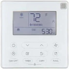
- Flexible airflow: User-selectable fan speeds (high, medium, low, turbo).
Installation and Mounting
Proper installation is critical for system performance:
- Leveling: Units must be level in all planes.
- Clearance: Maintain at least 24 inches of clearance for airflow.
- Support: Ensure adequate support for the weight of the fan coil.
- Drainage: Install drains in compliance with local sanitation codes.
Wiring
Power is supplied to the outdoor unit, which then powers the indoor unit. Follow these guidelines:
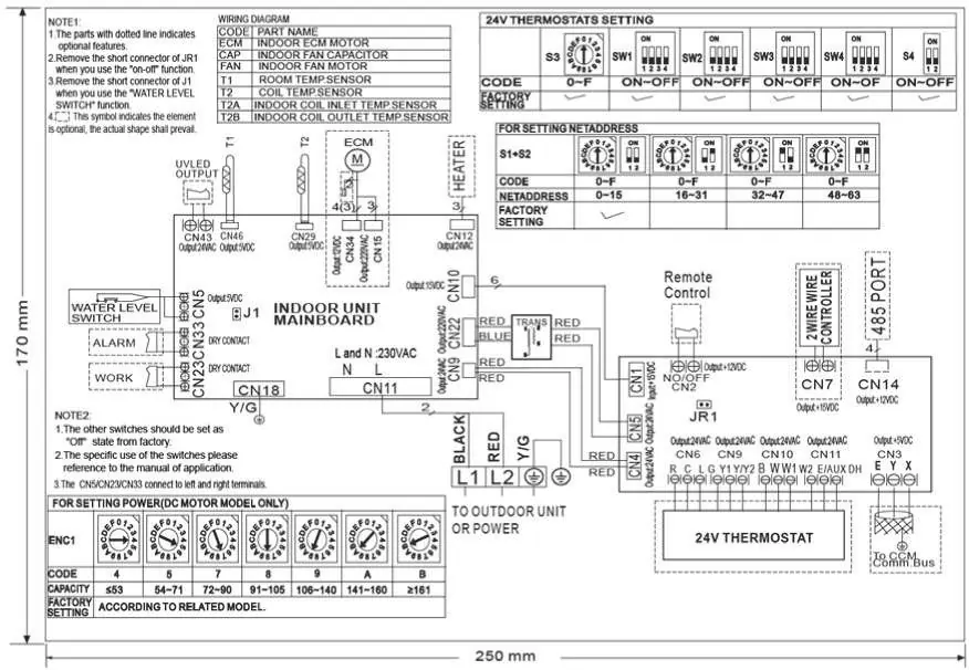
- Wiring Size: Size all wires per NEC or CEC and local codes using data from the outdoor unit (MCA/MOCP).
- Communication: In high electromagnetic field (EMF) areas, use 14/2 stranded shielded cable for communication lines to minimize interference.
- Disconnect: A disconnect switch may be required for the indoor unit depending on local codes.
- Auxiliary Heat: Electric heater kits require a separate power supply.
Control System
The system includes both wireless and wired remote controllers. The 24V interface allows integration with third-party thermostats. Note that a conventional 5-wire thermostat is required for standard operation, and a 2 heat/1 cool thermostat is required for electric heat applications.
Specifications
Refer to the specifications tables in the manual for detailed data on:
- Electrical: Voltage, phase, cycle, and MCA.
- Airflow: CFM values at various static pressures.
- Sound Pressure: dB(A) levels for cooling and heating operations.
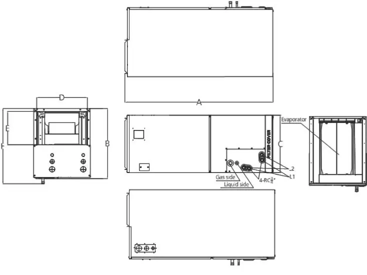
- Dimensions: Height, depth, and width for different model sizes (18K to 60K).
Manufacturer information
Viessmann Climate Solutions
Practical help
Common problems
Communication interference
If installed in a high EMF area, use 14/2 stranded shielded cable to replace L2 and (S) between the outdoor and indoor units, landing the shield on the ground in the outdoor unit only.
Unit not starting after power failure
The unit features an automatic restart function that restores the unit to the same operating conditions it was in at the time of failure.
Before use
- Ensure the unit is level in all planes.
- Verify adequate clearance for airflow (24 inches minimum).
- Check that wiring complies with NEC/CEC and local codes.
- Ensure a separate power supply is provided for electric heaters or other peripherals.
- Verify thermostat compatibility (24V interface requires a 5-wire thermostat).
Images and diagrams
- Fig 4-7: Multi-poise installation orientations (upflow, downflow, horizontal).
- Fig 9: Clearance requirements (24 inches minimum).
- Fig 14-15: Wiring diagrams for mainboard and 24V interface connections.
Model compatibility
- Requires a compatible outdoor unit.
- Electric heater kits require a separate power supply.
- 24V interface requires a 5-wire thermostat (2 heat/1 cool for electric heat applications).

Manual page author
Emily Carter
User documentation editor
Prepares concise manual descriptions and highlights the most useful setup, operation, and maintenance information for readers.