Accessories / Mounts & Stands
Installation and User Guide for Vogel's 062.287X Business & VC Trolley
Comprehensive installation and user guide for the Vogel's 062.287X Business & VC Trolley. Includes assembly steps, safety warnings, weight limits, height adjustment, and control box reset procedures.
Table of contents
Manual images
Click an image to enlargeQuick guide
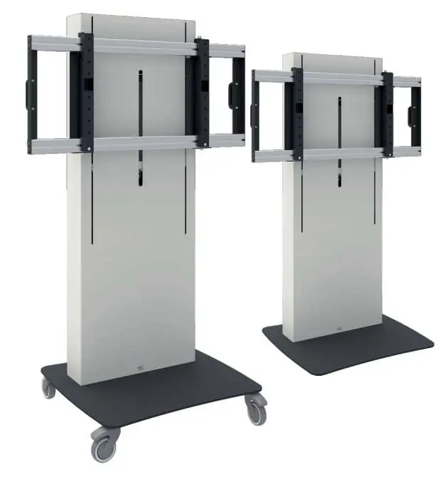
The Vogel's 062.287X Business & VC Trolley is designed for professional audiovisual equipment. Important: The maximum load capacity is 100 kg (220.5 lbs). The system has a duty cycle of 10% (maximum 2 minutes of continuous use followed by 50 minutes of rest). Always ensure the trolley is used on a level surface and that two people are present when moving the unit.
Safety instructions
- Weight Limit: Do not exceed the 100 kg maximum load. Exceeding this may cause instability, tipping, or equipment damage.
- Electrical Safety: Connect only to a properly grounded outlet. Always unplug before cleaning.
- Duty Cycle: Do not exceed 2 minutes of continuous operation followed by 50 minutes of rest.
- Children: Do not allow children to climb on the trolley. Keep remote controls and toys away from the lift mechanism.
- Operation: Do not place objects under the lift system. Ensure the power cord remains accessible at all times.
Installation
The installation must be performed by a certified installer. Ensure the structure can support five times the combined weight of all equipment.
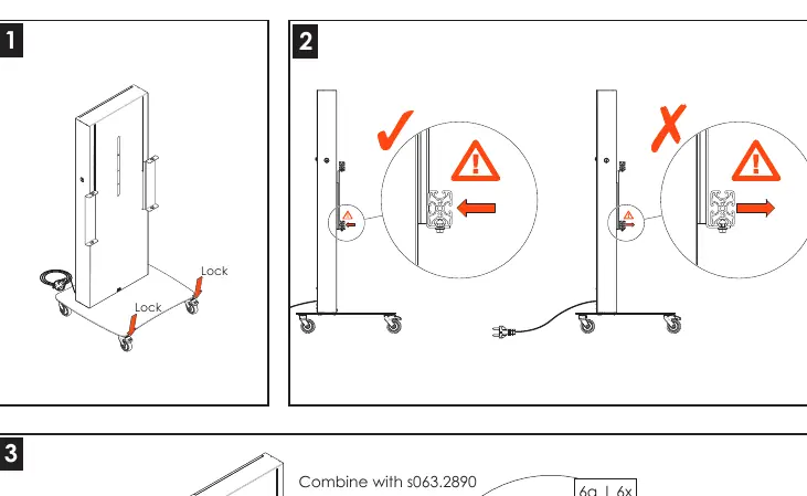
- Lock the wheel brakes before starting assembly.
- Assemble the trolley components according to the provided mounting instructions.
- Combine the trolley with the appropriate interface (e.g., S063.2890).
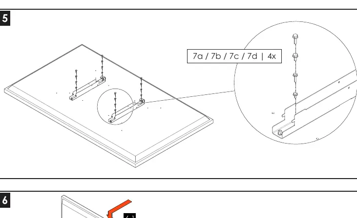
- Secure the display to the mounting interface using the provided screws (M6/M8 sizes).
- Fix all cables securely using the provided cable hooks and strain relief.
- Ensure all connections are tight and the trolley is stable before use.
Operation
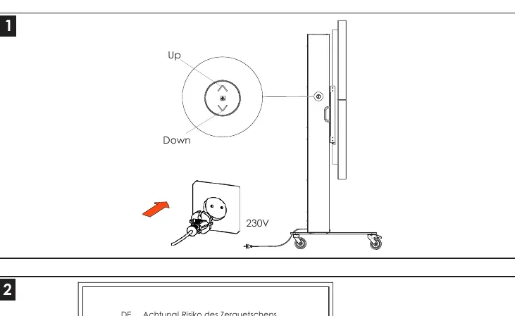
To adjust the height, use the control interface. Ensure the area under the lift is clear of objects. When moving the trolley, always disconnect the mains plug and use two people to maneuver the unit. Be cautious when passing over doorsteps or uneven surfaces.
Resetting the control box
If the lift system requires a reset:

- Check the connection from the remote to the control box and the power plug to the control box.
- Connect the power plug to the outlet.
- Move the lift to the lowest position.
- Release the down button.
- Push and hold the down button for 30 seconds to complete the reset.
Specifications
- Max Load: 100 kg / 220.5 lbs.
- Screen Sizes: 1x 55-86 inch or 2x 55-65 inch.
- Power Supply: 100-240V ~ 50/60Hz.
- Orientation: Landscape.
- Compatible Interfaces: S063.2890, S063.2891, S030.1035, S030.1045, S172.0008.
Wiring diagram
The system uses an RJ45 8-pin control cable. Refer to the wiring diagram for specific pin assignments (e.g., Blue+Green for Reference 1 Up, Blue+Red for Reference 1 Down). The total cable length is 1700 mm +/- 70 mm.

Practical help
Common problems
Lift system not responding
Perform a control box reset by holding the down button for 30 seconds at the lowest position.
Trolley is unstable or tipping
Verify that the total weight of the display and accessories does not exceed 100 kg.
Difficulty moving the trolley
Ensure two people are moving the unit, the mains plug is disconnected, and wheel brakes are unlocked.
Before use
- Verify the display weight is under 100 kg.
- Ensure the power outlet is properly grounded.
- Check that the area under the lift is clear of objects.
- Ensure two people are available for transport.
- Check that wheel brakes are locked during operation.
Specs in practice
- Power Supply
- 100-240V ~ 50/60Hz.
Images and diagrams
- The wiring diagram details the RJ45 8-pin control cable pinout for the lift system.
- Specific wire color pairs correspond to 'Up' and 'Down' reference signals.
Model compatibility
- Compatible with VESA mounts 1000x400 and 2000x400.
- Supports specific Cisco Webex Board Pro models.
- Landscape orientation only.

Manual page author
Michael Turner
Technical manual editor
Reviews PDF manuals for structure, safety notes, and practical product details so readers can find the right information quickly.