Automotive / Parts & Accessories
Volkswagen Cabriolet Digifant ECU DIY Guide
A comprehensive DIY guide for Volkswagen Cabriolet Digifant I and II engine control units. Includes diagnostic procedures, fault code definitions, ECU reset instructions, and detailed pinout diagrams.
Table of contents
Manual images
Click an image to enlargeQuick Guide to Digifant Diagnostics
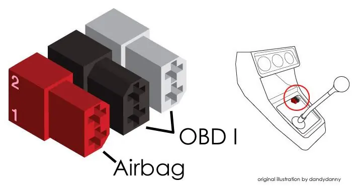
This guide provides instructions for diagnosing and resetting the Digifant I and II engine control units (ECU) in Volkswagen Cabriolet vehicles. The primary diagnostic method involves using a jumper wire to access the OBD I fault codes via the diagnostic ports located below the shift boot.
ECU Identification
The document distinguishes between two main systems:
- Digifant I: Typically found in 1991-1993 California models. Uses a 38-pin connector.
- Digifant II: Typically found in 1990-1993 49-state/International models. Uses a 25-pin connector.
Pulling Fault Codes (Jumper Method)
- Access the diagnostic ports located below the shift boot.
- Switch the ignition to ON.
- Connect the jumper tool: Connect Black pin 1 (brown wire) to White pin 1 (yellow wire).
- Wait 5 seconds for the OBD CHECK light to begin flashing.
- Remove the jumper, but leave the ignition ON.
- Record the sequence of flashes.
- The sequence ends when code 4444 or 0000 appears.
- Switch the ignition OFF to end the display.
Clearing Fault Code Memory
- Ensure the ignition is OFF.
- Connect the jumper tool: Black pin 1 (brown wire) to White pin 1 (yellow wire).
- Switch the ignition ON.
- Wait 5 seconds, then remove the jumper.
- The OBD CHECK light should flash code 4444.
- Switch the ignition OFF.
Resetting the Digifant I ECU
The ECU must be returned to reference settings if the coolant temp sensor was disconnected while running, or if the ECU, airflow sensor, throttle valve potentiometer, or throttle body were replaced.
Requirements before starting:
- Engine at normal operating temperature (80°C); radiator fan must have cycled on at least once.
- Exhaust system free of leaks.
- Idle stabilization system in proper operating condition.
- All electrical accessories switched off.
- Engine running.
Reset Procedure:
- Disconnect the crankcase ventilation hose from the emission control valve on top of the valve cover, then plug the hose.
- Start the engine and let it idle.
- Disconnect the blue coolant temp sensor.
- After one minute, reconnect the coolant temp sensor.
- Stop the engine.
- Unplug and reconnect the crankcase ventilation hose.
- Check and clear the OBD fault memory.
OBD I Fault Codes
- 4444: No faults recorded.
- 2141 / 2142: Knock sensor (defective sensor or wiring).
- 2212: Throttle valve potentiometer (defective potentiometer or wiring).
- 2312: Coolant temperature sensor (defective sensor or wiring).
- 2322: Intake air temperature sensor (defective sensor or wiring).
- 2323: Airflow sensor potentiometer (defective sensor or wiring).
- 2341 / 2342: Oxygen sensor (control exceeded or faulty sensor/wiring).
- 4411: Fuel injector (check wiring or injectors).
- 1111: Control unit (defective).
- 0000: End of fault code sequence.
Practical help
Common problems
Knock sensor fault (2141/2142)
Check the knock sensor and its wiring; ensure the control unit is recognizing the knock signal.
Oxygen sensor fault (2341/2342)
Check for air intake system leaks, verify CO adjustment, and inspect sensor wiring.
Fuel injector fault (4411)
Inspect fuel injector wiring and the injectors themselves.
Throttle valve potentiometer fault (2212)
Check the potentiometer and associated wiring.
Before use
- Ensure engine is at normal operating temperature (80°C).
- Verify the radiator cooling fan has cycled on at least once.
- Ensure the exhaust system is free of leaks.
- Confirm the idle stabilization system is in proper operating condition.
- Switch off all electrical accessories.
- Ensure the engine is running for the reset procedure.
Images and diagrams
- Diagnostic ports are located below the shift boot.
- Jumper method requires connecting Black pin 1 (brown wire) to White pin 1 (yellow wire).
Model compatibility
- Digifant I: 1991-1993 California models (38-pin ECU).
- Digifant II: 1990-1993 49-state/International models (25-pin ECU).

Manual page author
David Miller
Documentation analyst
Organizes user manual content into clear summaries, with attention to model details, product context, and everyday usability.