Home Appliances / Cooktops Hobs
Service Manual for Whirlpool AKM 160/IX/03 Gas Hob
Technical service manual for the Whirlpool AKM 160/IX/03 gas hob. Includes exploded views, wiring diagrams, spare parts list, and technical specifications for qualified technicians.
Table of contents
Manual images
Click an image to enlargeImportant Information for Technicians
This documentation is intended exclusively for qualified technicians who are familiar with the relevant safety regulations. It provides the necessary technical data, spare parts identification, exploded views, and wiring diagrams required for the maintenance and repair of the Whirlpool AKM 160/IX/03 gas hob.
Technical Specifications
Electrical Connection: 240 V, 50 Hz.
Dimensions:
- Height: 85 mm
- Width: 590 mm
- Depth: 500 mm
Built-in and Cut-out Dimensions:
- Built-in Height: 45 mm
- Cut-out Width: 570 mm
- Cut-out Depth: 480 mm
Weight: 8 kg (Gross).
Gas Configuration
The appliance supports different gas types. Ensure the correct injector markings are used based on the gas supply:
- Natural Gas (Methane) G20: Requires 10 mbar pressure. Injector markings: 165 (ultra rapid), 118 (medium), 90 (small).
- LPG (Propane) G31: Requires 27.5 mbar pressure. Injector markings: 102 (ultra rapid), 70 (medium), 54 (small).
Spare Parts and Assembly
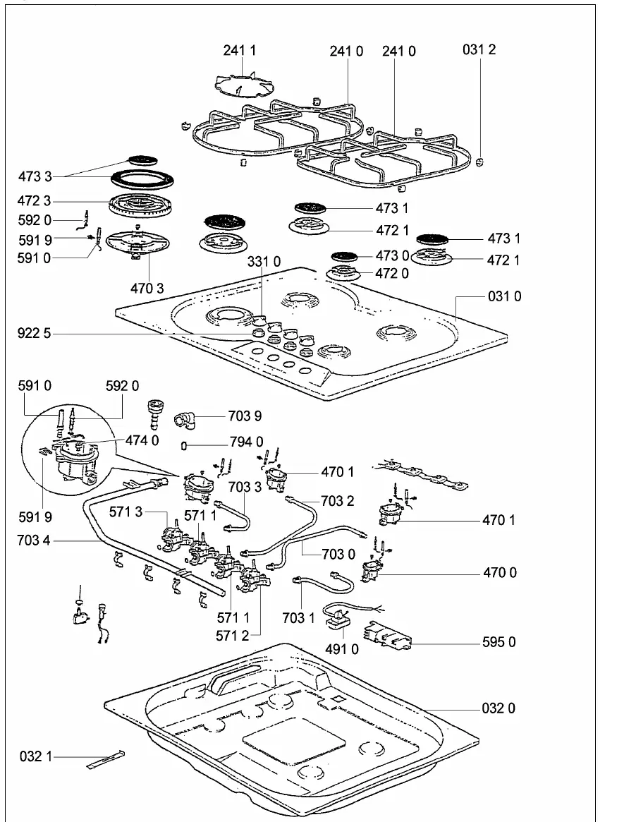
The manual includes a comprehensive spare parts list referencing 12NC codes for components such as burners, grids, spark plugs, thermocouples, and valves. An exploded view diagram is provided to assist in the identification and assembly of these parts.
Electrical Wiring
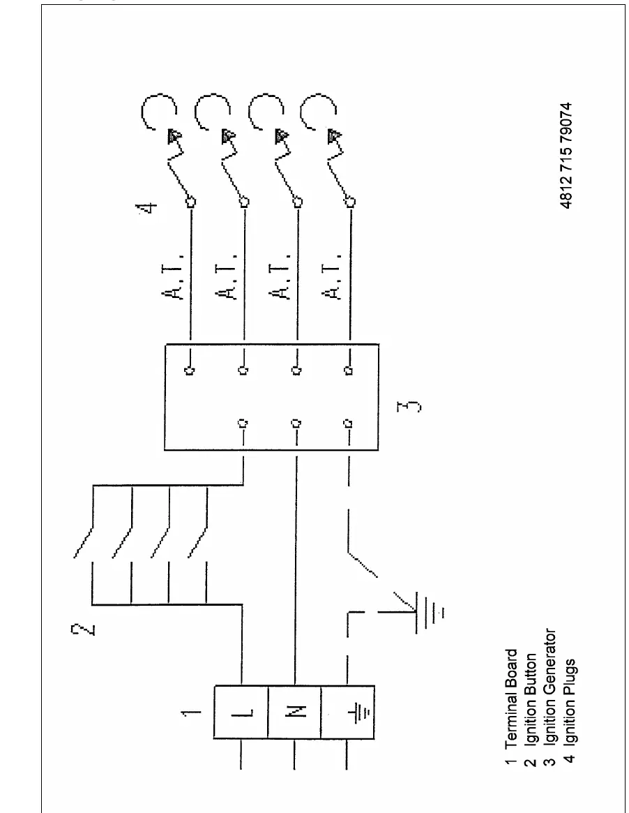
A wiring diagram is included to illustrate the electrical connections between the terminal board, ignition button, ignition generator, and spark plugs. Ensure all electrical work is performed according to safety standards.
Manufacturer information
Whirlpool Corporation
Practical help
Common problems
Incorrect burner performance or flame quality
Verify that the correct injector marking is installed for the specific gas type (Natural Gas vs LPG) and burner size.
Ignition failure
Check the wiring connections between the ignition button, generator, and spark plugs as shown in the wiring diagram.
Gas pressure issues
Ensure the gas supply pressure matches the required 10 mbar for Natural Gas (G20) or 27.5 mbar for LPG (G31).
Before use
- Verify the gas type (Natural Gas or LPG) matches the local supply.
- Check that the electrical supply is 240V, 50Hz.
- Ensure the cut-out dimensions (570x480 mm) are correct for installation.
- Confirm all burner components (spreaders, covers) are correctly positioned.
Show more Show less
Specs in practice
- Injector marking
- The specific size of the gas nozzle required for the burner to operate correctly with a specific gas type.
- Rated heat capacity
- The power output of the burner in Watts (W).
- Gas pressure
- The required pressure in mbar for the gas supply to ensure safe and efficient combustion.
Images and diagrams
- The exploded view illustrates the assembly of the hob, including the placement of grids, burners, and internal gas/electrical components.
- The wiring diagram shows the electrical path from the terminal board through the ignition button and generator to the spark plugs.
Model compatibility
- This manual is for qualified technicians only.
- Specifications are subject to modification.

Manual page author
David Miller
Documentation analyst