Power / Solar Panels
Installation Guide for Xantrex 110W Solar Flex Panel
Quick installation and maintenance guide for the Xantrex 110W Solar Flex Panel (781-0110). Includes wiring diagrams, mounting instructions, and troubleshooting steps.
Table of contents
Manual images
Click an image to enlargeImportant Information
The Xantrex 110W Solar Flex Panel is designed for use on vehicles such as RVs, trucks, and boats. Before installation, ensure the power system is designed by a certified solar system technician. All wiring must comply with local and national electrical codes. Do not ground any PV conductors and do not install the panel on residential structures.
Installation
Planning: Draw your power system layout on paper. Identify vehicle cable entry points and locate a suitable, moisture-free area for the charge controller.
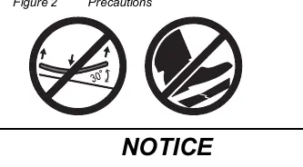
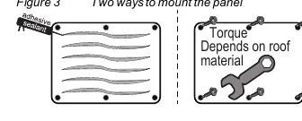

Mounting: Clean and degrease the roof surface with isopropyl alcohol. You can mount the panel using an industrial-grade outdoor UV-rated adhesive sealant or by using screws and washers. If using screws, apply waterproof sealant around the screw holes and heads to prevent water ingress. Precautions: Do not bend the panel more than 30 degrees and do not step on the cells with hard footwear.
Wiring
Connection: Cover the solar panel with a blanket or box to de-energize it before connecting. Use MC4-type connectors for the PV cables. Ensure correct polarity: Red (+) to positive, Black (-) to negative. Secure all cables with clamps or ties. Torque connections to 1.2 N-m (10.6 lb-in).
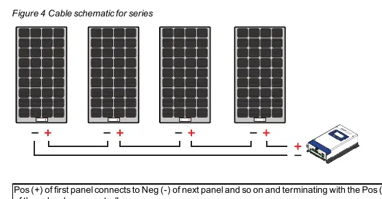
Configurations: Panels can be wired in series, parallel, or a combination of both depending on your charge controller requirements (PWM or MPPT).
Maintenance and Care
Perform monthly visual inspections for sharp objects, corrosion, or burnt hotspots. Ensure all mounting hardware is tight. Clean the panel in the early morning or evening when cool using a soft cloth, water, and mild detergent. Do not use abrasive materials, chemicals, or pressure washers.
Troubleshooting
If the battery does not charge, check for shading, loose DC cable connections, or a blown fuse. If the in-line fuse on the 10AWG positive battery cable blows, replace it with a 30A/32V green ATC blade fuse.
Specifications
Model: 781-0110. Dimensions: 39.6 x 26.9 x 0.12 inches. Weight: 5.5 lbs. Max Power: 110W. Open Circuit Voltage: 19.49V. Short Circuit Current: 5.95A. Safety: Class III PV Module.
For service, contact Xantrex at 1-800-670-0707 or visit http://www.xantrex.com.
Official resources from the manual
Practical help
Common problems
Battery does not get charged even when sunlight is present.
Check for partial shading on the panel, ensure DC cable connections are tight, or check if the in-line fuse is blown (replace with 30A/32V green ATC blade fuse).
Before use
- Plan the power system layout on paper.
- Gather necessary tools: drill with hex bits, wrench set, and torque driver.
- Verify the roof surface is clean, dry, and degreased.
- Ensure the charge controller is located in a moisture-free area.
- Cover the panel with a blanket during installation to prevent electrical hazards.
Specs in practice
- Maximum Power (STC)
- 110W - The peak power output under standard test conditions.
- Open Circuit Voltage
- 19.49V - The voltage of the panel when not connected to a load.
- Short Circuit Current
- 5.95A - The maximum current the panel can produce.
Images and diagrams
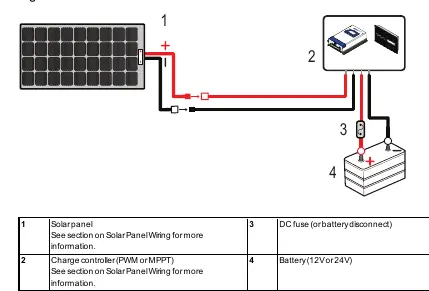
- Figure 1: Basic cable schematic showing the connection path from the solar panel through the charge controller and fuse to the battery.
- Figure 4: Series wiring configuration for multiple panels.
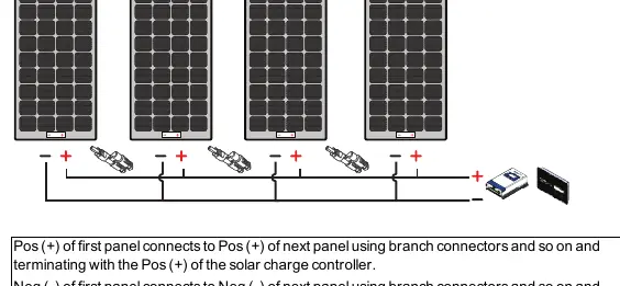
- Figure 5: Parallel wiring configuration using branch connectors.
- Figure 6: Combination wiring configuration for multiple strings.
Model compatibility
- Compatible with 12V and 24V battery systems.
- Requires a 30A PWM or MPPT charge controller.
- Uses MC4-type connectors for PV cabling.

Manual page author
David Miller
Documentation analyst
Organizes user manual content into clear summaries, with attention to model details, product context, and everyday usability.